


Reelmaster 7000Page 5 -- 18Electrical System
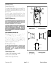
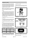
Fuses
Your Reelmaster 7000 uses numerous fuses for circuit
protection. The fuses are located in two (2) areas of the
machine. Most of the fuses reside in the power center
behind the operator’s seat. An in--line fuse holder lo-
cated in the wire harness near the engine starter motor
holds an additional fuse (F5--1) that protects the engine
run solenoid pull coil circuit.
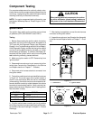
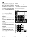
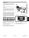
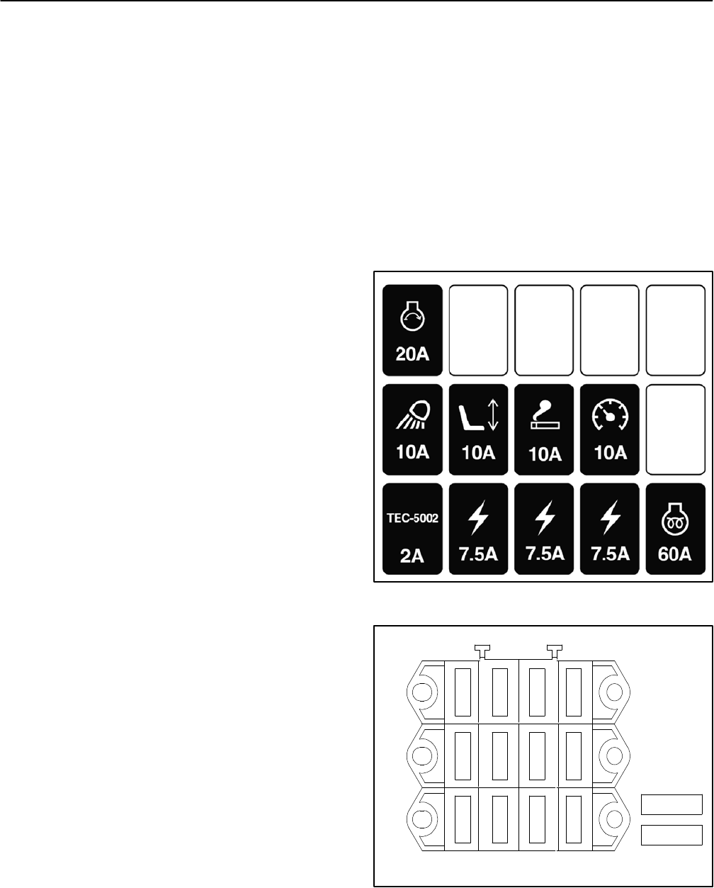
Fuse Identification and Function (Figs. 17 and 18)
Fuse F1--1 (20 Amp) protects power supply to engine
starter motor circuit.
Fuse F1--2 position availablefor optionalflow divider kit.
Fuse F1--3 position available for optional kit.
Fuse F1--4 position available for optional kit.
Fuse F2--1 (10 Amp) protects power supply to the light
circuit.
Fuse F2--2 (10 Amp) protectspower supply to the oper-
ator seat circuit.
Fuse F2--3 (10 Amp) protects power supply to the pow-
erpoint.
Fuse F2--4 (10 Amp) protects power supply to the main
power circuit.
Fuse F3--1 (2 Amp) protects logic power circuit to the
TEC controller.
Fuse F3--2 (7.5 Amp) protects power supply to the TEC
controller outputs.
Fuse F3--3 (7.5 Amp) protects power supply to the TEC
controller outputs.
Fuse F3--4 (7.5 Amp) protects power supply to the TEC
controller outputs.
Fuse M1 (60A) protects power supply to the glow plug
circuit.
Fuse M2 position available for operator cab option.
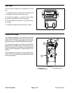
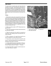
Fuse F5--1 (in--line 40A) protects power supply for the
engine run solenoid pull coil.
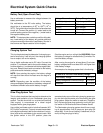
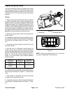
Fuse Testing
1. Make sure that ignition switch is OFF and key is re-
moved from switch.
2. Remove power center cover from operator platform
to access fuses.
3. Remove fuse from fuse block for testing. Fuse
should have continuity across the terminals.
4. After fuse testing is completed, install and secure
power center cover.
Figure 17
Figure 18
4321
FRONT
F3
F2
F1
2A
7.5A
7.5A
7.5A
10A
10A
10A
10A
20A
OPTION
OPTION
OPTION
M1 (60A)
M2 (option)