


Reelmaster 7000 Page 5 -- 33 Electrical System
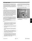
Hydraulic Solenoid Valve Coils
Numerous hydraulic solenoid valve coils are used on
the hydraulic control manifolds ofReelmaster 7000 ma-
chines. When energized by the TEC controller, these
coils provide hydraulic circuit control.
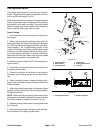
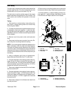
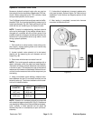
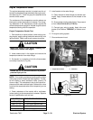
Two(2)differentsolenoidvalvecoilsareusedontheRe-
elmaster 7000. A coil can be identified by measuring it’s
height anddiameter (Fig. 46). Testingof the coils can be
done with the coil remaining on the hydraulic valve.
NOTE: To assist in troubleshooting, identical solenoid
coils can be exchanged. If the problem follows the ex-
changed coil, a problem with the coil likely exists. If the
problem remains unchanged, something other than the
solenoid coil is the problem source (e.g. switch, circuit
wiring, hydraulic problem).
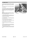
Testing
1. Park machine on a level surface, lower cutting units,
stop engine, engage parking brake and remove key
from the ignition switch.
2. Locate hydraulic valve solenoid coil to be tested.
Identify coil by measuring the coil diameter and coil
height (Fig. 46).
3. Disconnect wire harness connector from coil.
NOTE: Prior to taking small resistance readings with a
digital multimeter, short the meter test leads together.
The meter will display a small resistance value (usually
0.5 ohms or less). This resistance is due to the internal
resistance of the meter andtest leads. Subtract this val-
ue from fromthe measured value of the componentyou
are testing.
4. Using a multimeter (ohms setting), measure resis-
tance between the two (2) connector terminals on the
solenoid valve coil. The correct resistance for the sole-
noid coil is identified below:
COIL
DIAMETER
COIL
HEIGHT
COIL
RESISTANCE
1.840 inch
(46.7 mm)
1.960 inch
(49.9 mm)
7.1 ohm
1.410 inch
(35.8 mm)
1.430 inch
(36.3 mm)
8.8 ohm
NOTE: Solenoid coil resistance should be measured
with solenoidat approximately68
o
F(20
o
C).Resistance
may be slightly different than listed at different tempera-
tures. Typically, a failed solenoid coil will either be
shorted (very low or no resistance) or open (infinite re-
sistance).
5. If solenoid coil resistance is incorrect, replace sole-
noid (see Hydraulic Solenoid Valve Coil Removal and
Installation in the Service and Repairs section of this
chapter).
6. After testing is completed, connect wire harness
connector to the solenoid coil.
Figure 46
COIL
DIAMETER
COIL
HEIGHT
Electrical
System