


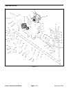
Reelmaster 7000Page 6 -- 12Axles, Planetaries and Brakes
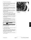
F. Lightly oilbearing journals on spindle shaft. Slide
housing assembly onto spindle (item 1) taking care
to not damage seal or spindle. Make sure that inner
bearing in housing fully seats against spindle shaft
shoulder.
G. Install outer bearing cone (item 12) onto spindle.
NOTE: Theplanetary shim kit includesthe retaining
ring and several thrust washers with thickness in in-
cremental steps of 0.004 inch (0.10 mm).
H. Measurethicknessofthrust washer(item14) that
was removed during disassembly. Choose new
thrustwasherofequalthicknessor thenextavailable
thickness from thrust washers in the shim kit.
I. Apply a light coating of oil to spindle shaft, thrust
washer (item 14) and new retaining ring ( item 15).
Install thrust washer onto spindle shaft.
WARNING
If retaining ring (item 15) is not fully installed in
spindle groove, loss of wheel and personal inju-
ry may result.
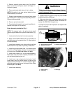
J. Carefully install new retaining ring (item 15) into
the spindle shaft groove taking care to not distort
ring. If the proper thrust washer has been installed,
the retaining ringshould fit tightly between thethrust
washer and spindle groove. Tap the OD of the re-
taining ring starting in the center and working out to-
ward each end to ensure that the retaining ring is
properly seated into the spindle groove. Make sure
that retaining ring ID is fully seated to spindle shaft
groove.
K. After retaining ring is installed, make sure that
there is no endplay in assembly. If required, remove
retaining ring and install a thrust washer of different
thickness to adjust endplay.
L. Install new O--ring (item 13) into groove in hous-
ing.
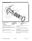
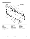
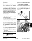
4. Install secondary carrier (item 28), secondary gear
(item 27) and primary carrier (item 26) making sure that
carrier gear teeth align with ring gear and spline on
spindle shaft.
5. If primary gear (item 24) was removed from drive
shaft,slidegearonto shaftandsecurewithretaining ring
(item 23).
6. Install drive shaft assembly (items 25, 24 and 23)
making sure that drive shaft spline aligns with carrier
gears.
7. Install thrust plug (item 21) and thrust washer (item
22) into end cap (item 20). Make sure that thrust plug
and thrust washer are captiveon inside of end cap (item
20).
8. Install new O --ring ( item 13) to end cap and then
install end cap.Secure capwith retaining ring (item 17).
9. Check operation of planetary wheel drive. With a
constant turning force applied, rotation of the planetary
should be consistent. If there is more drag at certain
points, gears are not rolling freely and the planetary
shouldbe examinedfor improperassemblyor damaged
components.
10.If planetarywheel drive assembly is installed on ma-
chine:
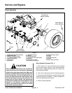
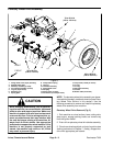
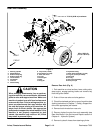
A. Install front wheel assembly.
Failure to maintain proper wheel lug nut torque
could result in failure or loss of wheel and may
result in personal injury.
WARNING
B. Lower machine to ground. Torque wheel lug nuts
in acrossing pattern from85 to 100ft--lb (116to 135
N--m).
C. Make sure drain plug is installed in bottom of
brake assembly. Fill planetary wheel drive/brake as-
sembly withSAE 85W--140 gearlube toproper level.
Capacity is approximately 16 oz. (0.47 l) per wheel.