


Reelmaster 7000 Hydraulic SystemPage 4 -- 111
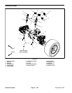
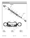
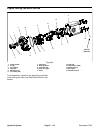
5. Removefour(4)capscrewsandwashersusedtose-
cure fan (item 13) to fan hub. Remove fan.
IMPORTANT: Make sure to not damage the radiator
or other machine components while loosening and
removing the fan motor and bracket assembly.
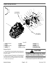
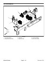
6. Remove cooling fan motor and bracket assembly.
A. To prevent contamination of hydraulic system,
thoroughly clean exterior of fan motor and fittings.
B. Disconnect hydraulic hoses from fan motor. Put
caps or plugs on fittings and hoses to prevent con-
tamination. Label hydraulic linesfor proper assemb-
ly.
C. Remove six (6) cap screws and flange nuts that
secure fan motor bracket to radiator.
D. Carefully remove fan motor and bracket assem-
bly from machine and place on suitable work sur-
face.
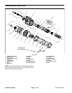
7. Removehexnut (item9)and washer(item8) thatse-
curefan hub tofan motor.Usesuitable puller tocarefully
remove fan hub from fan motor shaft. Locate and re-
trieve woodruff key.
8. Remove two (2) cap screws (item 20), flat washers
(item 21) and lock nuts (item 14) that secure fan motor
to fan motor bracket. Remove fan motor from bracket.
9. Ifhydraulic fittings are to beremoved from fan motor,
mark fitting orientation to allow correct assembly. Re-
move fittings from motor and discard O --rings.
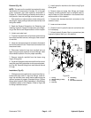
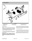
Installation (Fig. 82)
1. Iffittings were removedfrom fanmotor, lubricateand
place new O--rings onto fittings. Install fittings into port
openingsusingmarksmadeduringtheremovalprocess
to properly orientate fittings. Tighten fittings (see Hy-
draulic Fitting Installation in the General Information
section of this chapter).
2. Position fan motor to fan motor bracket and secure
with cap screws (item 20), flat washers (item 21) and
lock nuts (item 14).
3. Thoroughly clean tapered surfaces of fan motor
shaft and fan hub. Place woodruff key in slot in motor
shaft.
4. Position fan hub onto motor shaft and secure with
washer (item 8)and hex nut (item9). Torquenut from 27
to 33 ft --lb (37 to 44 N--m).
IMPORTANT: Make sure to not damage the radiator
or other machine components while installing the
fan motor and bracket assembly.
5. Carefullyposition fanmotor andbracketassembly to
radiator and secure with six (6) cap screws and flange
nuts.
6. Remove caps and plugs placed in hoses and fittings
during removal to prevent contamination. Connect hy-
draulic hoses to cooling fan motor (see Hydraulic Hose
and Tube Installation in the General Information section
of this chapter).
7. Position fan to fan hub and secure with four (4) cap
screws and washers.
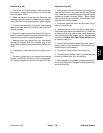
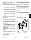
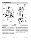
8. Install upper radiator shroud and air cleaner hose
(Fig.83). Makesurethat clearancebetweenshroud and
cooling fan is at least 0.180” (4.6 mm) at all points.
9. Lower and secure hood.
10.Check oil level in hydraulic reservoir and add correct
oil if necessary.
11.Follow Hydraulic System Start--up procedures (see
Hydraulic System Start--up in this section).
1. Radiator
2. Upper radiator shroud
3. Screw (4 used)
4. Flange nut (4 used)
5. Air cleaner hose
6. Screw
7. Flat washer
Figure 83
3
5
6
7
1
2
4
Hydraulic
System