


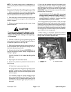
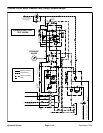
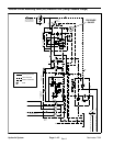
Reelmaster 7000 Hydraulic SystemPage 4 -- 39
NOTE: The traction charge circuit is designed to re-
place loss ofhydraulic fluid from the closed looptraction
circuit.
ProcedureforTractionCircuitChargePressureTest
1. Make sure hydraulic oil is at normal operating tem-
peraturebyoperatingthemachineforapproximatelyten
(10) minutes. Make sure the hydraulic tank is full.
2. Parkmachine onalevel surfacewith thecuttingunits
lowered and off. Make sure engine is offand the parking
brake is engaged.
3. Raise and support operator seat to access charge
pressure test port.
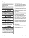
CAUTION
Prevent personal injury and/or damage to equip-
ment. Read all WARNINGS, CAUTIONS and Pre-
cautions for Hydraulic Testing at the beginning
of this section.
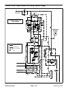
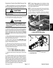
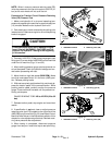
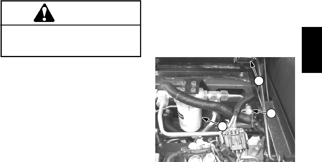
4. Connect a 1000 PSI (70 bar) pressure gauge onto
chargepressuretestport.Testportislocatedonhydrau-
lic tube near hydraulic oil filter (Fig. 28).
5. After installing pressure gauge, start engine and run
at low idle speed. Check for hydraulic leakage and cor-
rect before proceeding with test.
6. Move throttle to high idle speed (2850 RPM) with no
load on the hydraulic system. Identify charge pressure
reading on gauge:
GAUGEREADINGTOBE210 to 300 PSI (14.5 to
20.6 bar)
7. Stop engine and record test results.
8. If there is no pressure or pressure is low, check for
the following:
A. Restriction in gear pump intake line.
B. Charge reliefvalve in filtration and chargecontrol
manifold is leaking (see Filtration/Charge Control
Manifold Service in the Service and Repairs section
of this chapter).
C. If necessary, check for internal damage or worn
parts in gear pumpP3 (see Gear Pump P3 Flow Test
in thissection). NOTE:Steering andlift/lower circuits
would also be affected if gear pump P3 is worn or
damaged.
9. Also, with the pressure gauge still connected to the
charge pressure test port, monitor the gauge reading
while operating the machine in forward and reverse.
Start the engine and put throttle at full engine speed
(2850 RPM). Apply the brakes and push the traction
pedal forward, then reverse.
GAUGE READING TO BE within 20% of no--load
charge pressure measured in step 4 above (e.g.
if charge pressure in step 4 is 250 PSI (17.2 bar),
charge pressure in forward or reverse should be
from 200 to 250 PSI (13.8 to 17.2 bar)
10.If charge pressure is good under no load, but drops
below specification when under tractionload, the piston
(traction) pump,front wheelmotors and/orrear axle mo-
tor should be suspected of wear and inefficiency. When
thepumpand/or tractionmotor(s)are wornordamaged,
thechargepumpis notabletokeepupwithinternalleak-
age in traction circuit components.
11.When testing is completed, disconnect pressure
gaugefrommanifoldtestport.Install dustcaptotestport
fitting. Lower and secure operator seat.
1. Operator seat
2. Oil filter
3. Test port location
Figure 28
1
2
3
Hydraulic
System