


Reelmaster 7000 Page 5 -- 17 Electrical System
Component Testing
For accurate resistance and/or continuity checks, elec-
trically disconnect the component being testedfrom the
circuit (e.g. unplug the ignition switch connector before
checking continuity on the switch terminals).
NOTE: For engine component testing information, see
the Kubota Workshop Manual, Diesel Engine, 03--M--
DI--E3B.
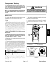
CAUTION
When testing electrical components for continu-
ity with a multimeter (ohms setting), make sure
that power to the circuit has been disconnected.
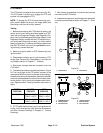
Ignition Switch
The ignition (key) switch on the console arm has three
(3) positions (OFF, ON/PREHEAT and START).
Testing
1. Before disconnecting the ignition switch for testing,
the switch and its circuit wiring should be tested as a
TEC input with the Diagnostic Display (see Diagnostic
Display in the Troubleshooting section of this chapter).
If the Diagnostic Display verifies that the ignition switch
and circuit wiring are functioning correctly, no further
switch testing is necessary. If, however, the Display de-
termines that the ignition switch and circuit wiring are
not functioning correctly, proceed with test.
2. Make sure ignition switch is OFF. Remove key from
ignition switch.
3. Disassemble console arm to gain access to ignition
switch (see Console Arm Disassembly in the Service
and Repairs section of Chapter 7 -- Chassis).
4. Disconnect wire harness electrical connector from
the ignition switch.
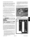
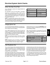
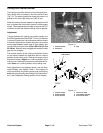
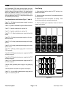
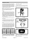
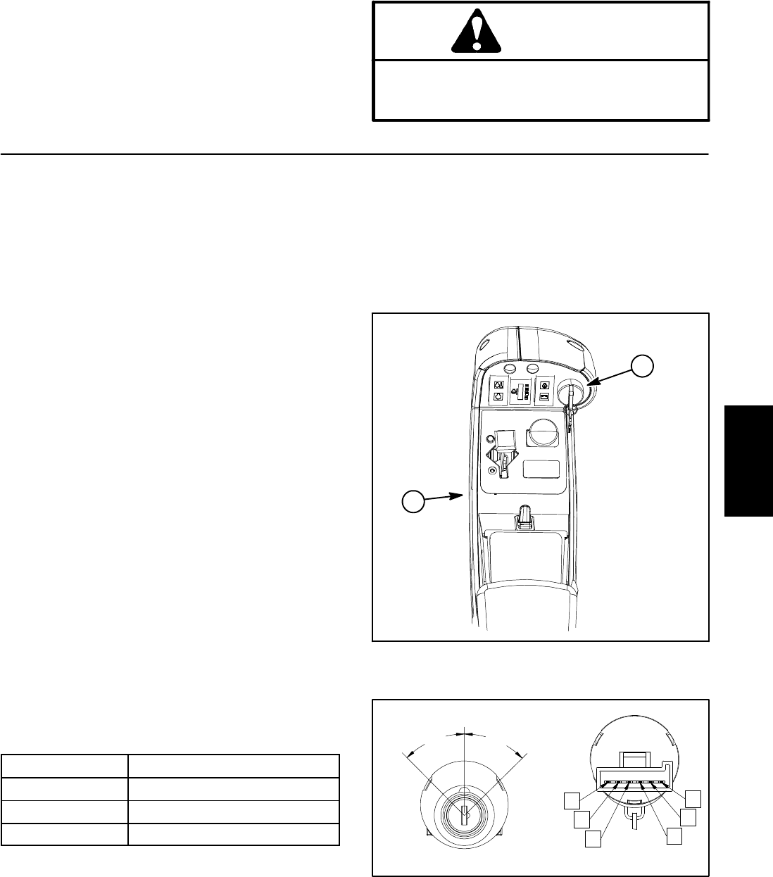
5. The ignition switch terminals are identifiedas s hown
in Figure 16. The circuit logic of the ignition switch is
shown in the chart below. With the use of a multimeter
(ohms setting), the switch functions can be tested to de-
termine whether continuity exists between the various
terminals for each switch position. Verify continuity be-
tween switch terminals. Replace switch if testing identi-
fies that switch is faulty.
POSITION
CIRCUIT
OFF NONE
ON/PREHEAT B+C+F, D+E
START A+B+C
6. If ignition switch tests correctly and circuit problem
still exists, check wire harness (see Electrical Schemat-
ics and Wire Harness Drawings in Chapter 9 -- Foldout
Drawings).
7. After testing is completed, connect the wire harness
connector to the ignition switch.
8. Assemble console arm (see Console Arm Assembly
in the Service and Repairssection of Chapter 7 -- C has-
sis).
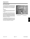
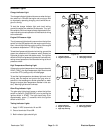
1. Console arm 2. Ignition switch
Figure 15
1
2
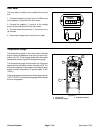
Figure 16
REAR VIEW
FRONT VIEW
A
B
C
D
E
F
START
OFF
ON/PREHEAT
45
o
45
o
Electrical
System