


Reelmaster 7000Page 5 -- 38Electrical System
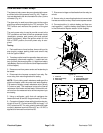
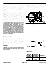
Fuel Stop Solenoid
Thefuelstopsolenoidused onyourReelmastermustbe
energized for the diesel engine to run. The solenoid is
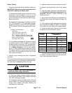
mounted to the injection pump on the engine (Fig. 55).
The TEC controller monitors the operation of the fuel
stop solenoid.The solenoid and its circuitwiring should
be tested as a controller output with the Diagnostic Dis-
play before following the testing procedure listed below
(see Special Tools and Troubleshootingin this chapter).
Testing
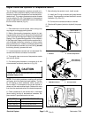
1. Park machine on a level surface, lower cutting units,
stop engine, apply parking brake and remove key from
ignition switch. Open hood to gain access to engine.
2. Disconnect wire harness connector from fuel stop
solenoid.
NOTE: The fuel stop solenoid may be removed from
the engine or tested in place.
3. If the solenoid is removed from the engine, make
sure that the solenoid plunger moves freely and is free
of dirt, debris and corrosion.
NOTE: Prior to taking small resistance readings with a
digital multimeter,short the test leads together.The me-
ter will display a small resistance value (usually 0.5
ohms or less). This resistance is due to the internal re-
sistance of the meter and test leads. Subtract this value
fromthe measured valueof thecomponent youare test-
ing.
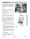
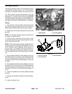
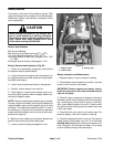
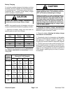
4. Using a digital multimeter (ohms setting), touch one
test lead to the pull coil terminal and the other test lead
to the fuel stop solenoid frame (ground) (Fig. 56). The
resistance of the pull coil should be less than 1 ohm (but
not zero).
5. Using a digital multimeter (ohms setting), touch one
test lead to the hold coil terminal and the other test lead
to the fuel stop solenoid frame (ground) (Fig. 56). The
resistance of the hold coil should be approximately 15
ohms.
6. If either coil resistance is incorrect, replace fuel stop
solenoid.
7. Connect wire harness connector to the fuel stop so-
lenoid.
8. Lower and secure hood.
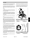
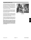
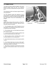
1. Injection pump 2. Fuel stop solenoid
Figure 55
1
2
1. Fuel stop solenoid
2. Pull coil terminal
3. Hold coil terminal
Figure 56
1
3
2