


Reelmaster 7000 Page 3 -- 17 Kubota D iesel Engine
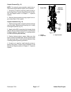
Coupler Removal (Fig. 12)
NOTE: The hydraulic pump assembly needs to be re-
moved from engine before coupler can be removed.
1. If engine is in machine, remove hydraulic pump as-
sembly(seePiston(Traction)PumpRemovalintheSer-
vice and Repairs section of Chapter 4 -- Hydraulic
System).
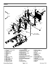
2. Remove flywheel plate and spring coupler from en-
gine using Figure 12 as a guide.
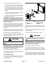
Coupler Installation (Fig. 12)
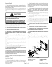
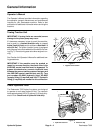
1. Position spring coupler to engine flywheel and align
mounting holes. Make sure that coupling hub is away
from engine flywheel (Fig. 13).
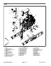
2. Apply Loctite #242 (or equivalent) to threads of bolts
(item6). Securecoupler toflywheel withsix (6)bolts and
hardened washers. Torque bolts in a crossing pattern
from 29 to 33 ft-- lb (40 to 44 N--m).
3. Position flywheel plate to engine. Make sure that
boss on plate is orientated down. Secure flywheel plate
with cap screws (item 7) and hardened washers using
a crossing pattern tightening procedure.
4. If engine is in machine, install hydraulic pump as-
sembly (see Piston (Traction) Pump Installation in the
Service and Repairs section of Chapter 4 -- Hydraulic
System).
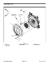
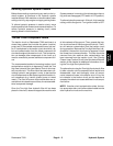
Figure 13
1. Coupler
2. Coupler hub
3. Engine flywheel
Engine Side Hydraulic
Pump Side
1
2
3
Kubota
Diesel Engine