


Reelmaster 7000
DPA Cutting Units
Page 8 -- 26
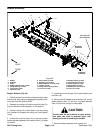
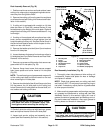
IMPORTANT: During cutting reel installation, keep
inner a nd outer bearing races aligned. If bearing
races are not aligned, binding will occur and reel
installation may cause bearing damage. Use reel
bearing installation tool (#117--0975) to help with
bearing alignment during reel installation.
3. Usingreelbearinginstallationtool(seeSpecialTools
in this chapter) to keep reel bearing aligned, carefully
slide thecutting reel withbearings and grease sealsinto
the RH side plate. Make sure that bearing is fully seated
into side plate.
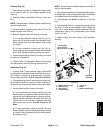
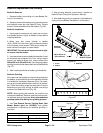
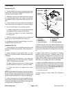
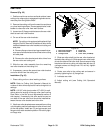
4. On LH side plate, loosen set screw and back--off
(loosen) bearing adjuster nut one complete turn (Fig.
31).
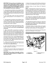
5. Usingreelbearinginstallationtool(seeSpecialTools
in this chapter) to keep reel bearing aligned, carefully
slide the LH side plate onto the cutting reel assembly,
front roller and rear roller. Make sure thatreel end inRH
side plate does not shift in position.
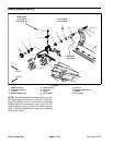
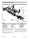
6. Install shoulder bolts (item 8) and flange nuts (item
24) that secure the LH side plate to the cutting unit
frame. Torque the shoulder bolts from 27to 33ft--lb (37
to 44 N --m).
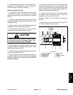
7. Apply Loctite #242 (or equivalent) to threads of
flange head screw that secures support tube, frame
spacer and carrier frame to LH s ide plate (Fig. 30).
Install screw and torque from 27 to 33 ft--lb (37 to 44
N--m). After tightening screw, check the clearance be-
tween the carrier frame and side plate. If clearance is
more than 0.090” (2.3 mm), remove flange head screw
and position shim(s) (part number 67--9410) between
carrier frame and side plate so that clearance is less
than 0.090” (2.3 mm). Make sure that the carrier frame
pivots freely after assembly.
8. Install cap screw and flat washer that secure rear
grass shield to LH side plate (Fig. 30). Torque screw
from 15 to 19 ft-- lb (20 to 25 N--m).
9. Secure the bedbar assembly to LH side plate (see
Bedbar Installation in this section).
10.Secure front and rear rollers to LH side plate (see
Front Roller Installation and Rear Roller Installation in
this section).
IMPORTANT: After cutting unitassembly, reel bear-
ings must be adjusted properly or damage to reel
bearings will occur.
11.Adjust reel bearings (see Reel Bearing Adjustment
in the Set --up and Adjustments section of this chapter).
12.Adjust cutting unit (see Cutting Unit Operator’s
Manual).
NOTE: The parallel position of the rear roller to the cut-
ting reel is controlled by the precision machined frame
and side plates of the cutting unit. If necessary, the cut-
ting unit side plates can be loosened anda slight adjust-
ment can be made to parallel the rear roller with the
cutting reel (see Leveling Rear Roller in the Set--Up and
Adjustments section of this Chapter).
13.If cutting unit is equipped with optional rear roller
brush, install brush components to left hand side plate
of cutting unit. See Rear Roller Brush in this section for
information on rear roller brush.
14.If weight was removed from cutting unit, install new
O--ring(item 12)on weight.Secure weight tocutting unit
side plate with two (2) c ap screws. Torque screws from
27 to 33 ft--lb (37 to 44 N--m).
15.Lubricate cutting unit grease fittings until grease
purges from relief valves in side plates. Initial greasing
may require several pumps of a hand grease gun.
16.Install cutting unit to the machine (see Cutting Unit
Removal and Installation in this section).
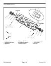
1. LH side plate
2. Threaded insert
3. Bearing adjuster nut
4. Set screw
Figure 31
1
2
3
4