


Reelmaster 7000 Page 7 -- 17 Chassis
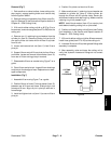
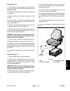
NOTE: Most of the seat suspension components can
be serviced with the seat suspension base mounted to
theseatplate.Iftheair springassembly(item6)requires
removal, the seat suspension base will have to be re-
moved from the seat plate.
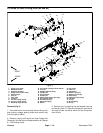
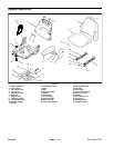
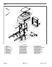
Disassembly (Fig. 15)
1. Park machine on a level surface, lower cutting units,
stop engine, apply parking brake and remove key from
the ignition switch.
2. Remove operator seat from seat suspension (see
Operator Seat Removal in this section).
3. Disconnect seat suspension electrical c onnector
from machine wire harness.
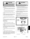
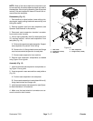
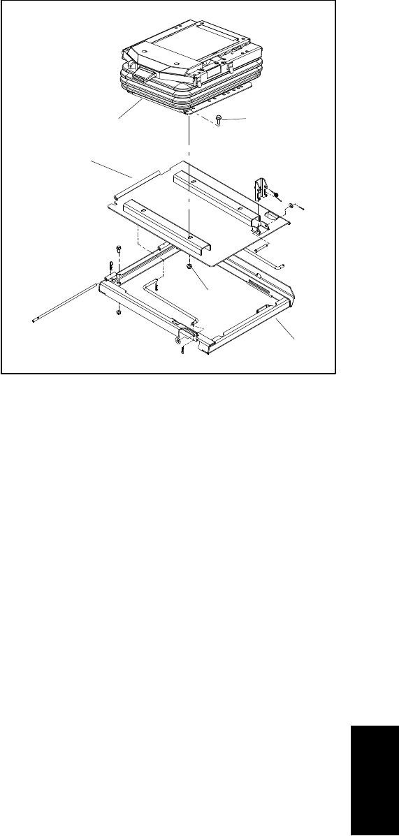
4. If the air spring assembly (item 6 ) or base plate (item
37) requires removal, remove seat suspension from
seat plate (Fig. 16):
A. Raise and support seat plate assembly. Support
seat suspension to prevent it from falling.
B. Remove four (4) flange head screws and flange
nuts that secure seat suspension to seat plate.
C. Remove seat suspension from machine.
5. Remove seat suspension components as needed
using Figure 15 as a guide.
Assembly (Fig. 15)
1. Install all removed seat suspension components us-
ing Figure 15 as a guide.
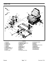
2. If seat suspension was removed from seat platform
(Fig. 16):
A. Position seat suspension onto seat plate.
B. Secureseat suspensionto seatplatew ith four(4)
flange head screws and flange nuts.
3. Install operator seat toseat suspension(see Opera-
tor Seat Installation in this section).
4. Make sure that seat electrical connectors are se-
cured to machine wire harness.
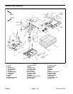
1. Seat frame
2. Flange nut (4 used)
3. Seat plate
4. Seat suspension
5. Flange screw (4 used)
Figure 16
1
3
5
4
2
Chassis