


Reelmaster 7000
DPA Cutting Units
Page 8 -- 13
Leveling Rear Roller
The precision machined components of the cutting unit
frame keep the rear roller and cutting reel in alignment
(parallel). If the side plates are disassembled or as the
cutting reel wears, a limitedamount of side plateadjust-
ment is possible to make sure that the cutting unit is
properly aligned.
1. Place the assembled cutting unit on a surface plate.
2. Make sure that bedknife is properly adjusted to cut-
ting reel.
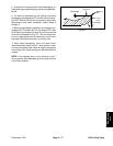
3. Using the surfaceplate, check if rear roller is level to
cutting reel by using a 0.005” (0.13 mm) shim at each
end of rear roller. If the shim will pass under the roller at
one end but not the other, a frame adjustment should be
made.
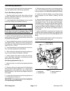
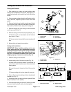
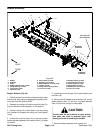
4. Loosen, but do not remove, the three (3) shoulder
bolts that securethe side plate to the frame oppositethe
side that is not level (Fig. 12).
5. Adjust the position of the side plate to parallel the
rear roller and cutting reel. Then, tighten the shoulder
bolts to a torque from 27 to 33 ft--lb (37 to 44 N--m).
6. Aftertighteningthe sideplate,recheck therearroller.
If necessary, loosen and adjust second side plate.
7. If rear roller is still not level after adjusting both side
plates, check to see if cutting reel is tapered (see Pre-
paring Reelfor Grinding in the Serviceand Repairs sec-
tionof this chapter).If cuttingreel is nottapered andrear
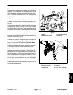
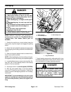
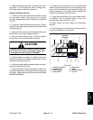
roller isnot level,a 0.010”shim (partnumber 107--4001)
is available to allow additional rear roller adjustment.
Use the shim on one side of the rear roller and install it
between the rear roller bracketand roller shim ( Fig. 13).
8. Afterleveling rearroller,complete cuttingunit set--up
and adjustment sequence.
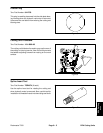
1. Bedbar
2. Bedbar adjuster screw
3. Spring tension lock nut
4. Shoulder bolt
Figure 12
2
4
1
3
4
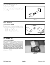
1. Rear roller assembly
2. Rear roller bracket
3. Carriage screw
4. Flange nut
5. Roller shim
6. 0.010” shim (if needed)
Figure 13
1
2
3
4
5
6
DPA Cutting
Units