


Reelmaster 7000 Hydraulic SystemPage 4 -- 19
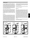
Raise Cutting Units
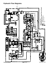
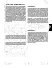
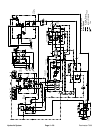
A four section gear pump is coupled to the piston (trac-
tion) pump. Gear pump section P3 supplies hydraulic
flow toboth thelift controlmanifoldand thesteering con-
trol valve. Hydraulicflow from this pump section is deliv-
ered to the circuits through a proportional flow divider
located in the fan c ontrol manifold. Maximum lift/lower
circuitpressureislimitedto 1700PSI(117bar) byarelief
valve (RV1) in the lift control manifold. Lift circuit pres-
sure can be monitored at the test fitting in lift control
manifold port G.
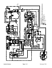
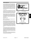
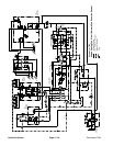
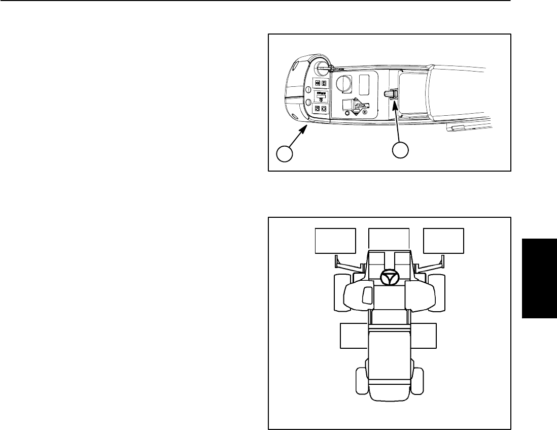
A single lift switch on the console arm is used to raise
and lower the five (5) cutting units (Fig. 10). The lift
switch acts as an input to the TEC controller to send
electrical outputs to appropriate lift control manifold so-
lenoid coils in order to raise or lower the cutting units.
When the cutting units are in a stationary position (not
raising or lowering), lift circuit flow from gear pump sec-
tion P3 bypasses the lift cylinders through the lift control
manifold solenoid valveS1 (de--energized). Return flow
from the manifold is routed to the oil filter and traction
charge circuit.
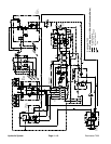
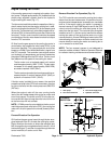
Raise Cutting Units
NOTE: The operator must be in the operator seat in or-
der to raise the cutting units.
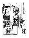
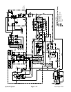
When the lift switch is moved to the raise position, sole-
noid valve S1along with solenoid valves S2, S3,S4 and
S5 are energized by the TEC controller. To allow the
front cutting units to be raised before the rear cutting
units, the controller slightly delays energizing solenoid
S5 after the lift switch is pressed. The energized sole-
noidvalves directgear pumpoilflow tothe rodendofthe
lift cylinders. The flow control orifice in the lift control
manifold port C3 is bypassed when raising the cutting
units.
Hydraulic pressure causes the lift cylinder shafts to re-
tract,and raisethe cuttingunits. Theflow controlorifices
in the junction manifold are bypassed when raising the
cutting units. Flow control orifices in the lift control man-
ifold (ports C2 and C4) control the cutting unit raising
speed by providing a restriction for the return flow from
the lift cylinders.
When the lift switch is released, solenoid valves S1, S2,
S3, S4 and S5 are de--energized and the lift cylinders
and cutting units are held in position.
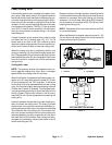
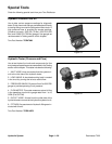
Figure 12
1
2
1. Console 2. Lift switch
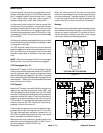
Figure 13
CUTTING UNIT LOCATIONS
#4 #1 #5
#3#2
Hydraulic
System