


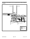

Reelmaster 7000 Hydraulic SystemPage 4 -- 61
The lift/lower circuit relief pressure test should be per-
formed to make sure that the cutting unit lift and lower
circuit relief pressure is correct.
Procedure for Lift/Lower Circuit Relief Pressure
Test
1. Make sure hydraulic oil is at normal operating tem-
peraturebyoperatingthemachineforapproximatelyten
(10) minutes. Make sure the hydraulic tank is full.
2. Parkmachine onalevel surfacewith thecuttingunits
fully lowered. Apply the parking brake and stop engine.
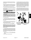
CAUTION
Prevent personal injury and/or damage to equip-
ment. Read all WARNINGS, CAUTIONS and Pre-
cautions for Hydraulic Testing at the beginning
of this section.
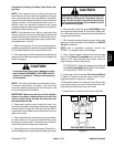
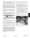
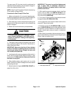
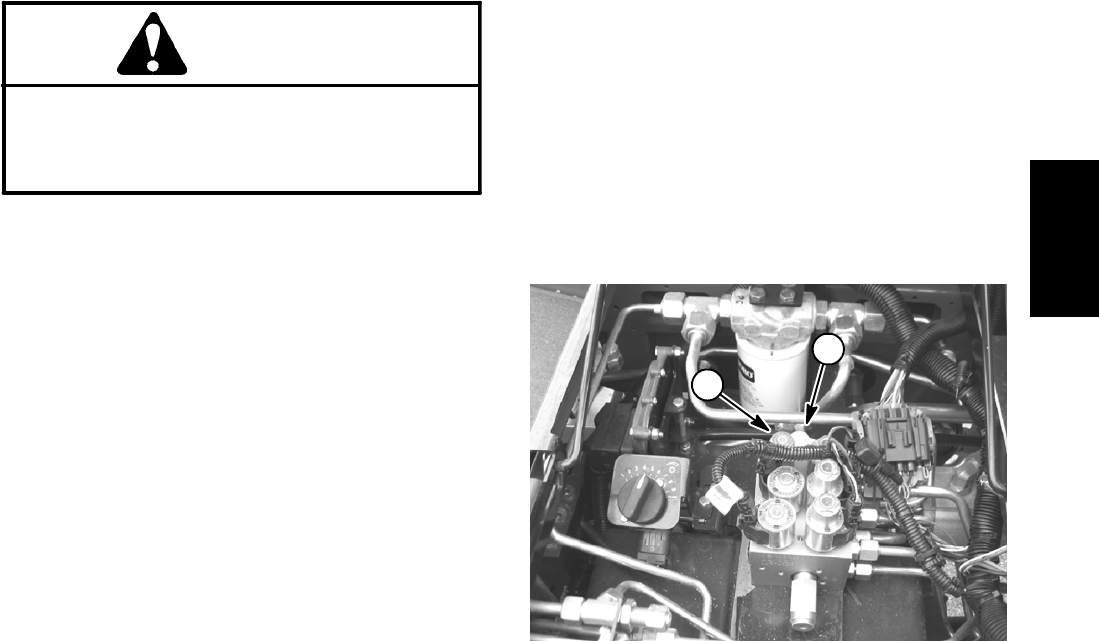
3. Raise and support hood to gain access to lift control
manifold (Fig. 45). Connect a 5000 PSI (350 bar) pres-
sure gauge with hydraulic hose attached to lift manifold
test port G. Routegauge hose to allow hood to be safely
lowered.
4. After installing pressure gauge, start engine and run
at low idle speed. Check for hydraulic leakage and cor-
rect before proceeding with test.
5. Move throttle to full engine speed (2850 RPM).
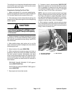
6. While sitting onthe seat, move lift switch toraise and
allowthe cuttingunits tofullyraise. Momentarilyholdthe
switch with the lift cylinders fully retracted while looking
at the pressure gauge.
7. When the lift cylinders are fully retracted (cutting
units fully raised) and the relief valve lifts, the pressure
gauge needle will momentarily stop. System pressure
asthereliefvalveRV1opensshouldbebeapproximate-
ly 1700 PSI (117 bar). Release lift switch to the neutral
position after observing relief valve pressure.
NOTE: Iflift switch continues tobe pressed after the re-
lief valve has opened, system pressure can increase
higher than relief pressure.
8. Stop the engine and record test results.
9. If specification is not met, clean or adjust relief valve
RV1 located in the lift control manifold (see Lift Control
Manifold Service in the Service and Repairs section of
this chapter).
A. If pressure is too high, adjust relief valve RV1 to
reduce lift/lower circuit relief pressure (see Adjust
Control Manifold Relief Valves in the Adjustments
section of this chapter).
B. If pressure is too low, check for restriction in gear
pump intake line. Check the lift cylinders for internal
leakage. If pump intake line is not restricted and lift
cylinders are not leaking, adjust relief valve RV1 to
increase lift/lower circuit relief pressure (see Adjust
Control Manifold Relief Valves in the Adjustments
section of this chapter).
C. If pressure is still too low after relief valve adjust-
ment, lift cylinder(s) or gear pump P4 should besus-
pected of wear or damage.
10.After testing is completed, remove pressure gauge
frommanifold testport.Install dustcap totestport fitting.
Lower and secure hood.
1. Test port G1 2. Relief valve RV1
Figure 45
1
2
Hydraulic
System