


Reelmaster 7000Hydraulic System Page 4 -- 86
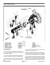
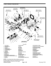
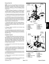
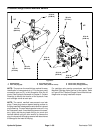
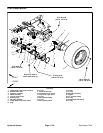
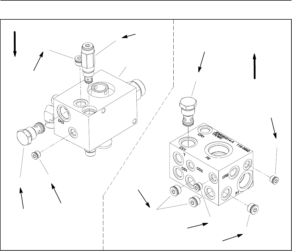
Filtration/Charge Control Manifold Service
1. Manifold body
2. Zero leak plug (#8)
3. Zero leak plug (#6)
4. Check valve (reservoir return)
5. Check valve (filter bypass)
6. Check valve (charge pressure)
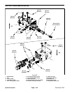
Figure 63
25 ft--lb
(34 N--m)
50 ft--lb
(68 N--m)
25 ft--lb
(34 N--m)
35 ft--lb
(47 N--m)
UP
2
3
6
1
5
4
2
2
3
3
35 ft--lb
(47 N--m)
25 ft--lb
(34 N--m)
50 ft--lb
(68 N--m)
25 ft--lb
(34 N--m)
50 ft--lb
(68 N--m)
UP
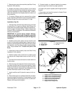
NOTE: The ports on the manifold are marked for easy
identification of components (e.g. P2 is the gear pump
connection port and P1 is the connection from the oil
cooler).SeeHydraulicSchematic inChapter9 -- Foldout
Drawings to identify the function of the hydraulic lines
and cartridge valves at each port.
NOTE: The control manifold uses several zero leak
plugs. These plugs have a tapered sealing surface on
theplug headthat isdesigned toresistvibration induced
plugloosening. Thezeroleak plugsalso havean O--ring
as a secondary seal. If zero leak plug removal is neces-
sary, lightly rap the plug head using a pin punch and
hammer before using an allen wrench to remove the
plug:the impact willallow plugremoval with lesschance
of damage to the head of the plug.
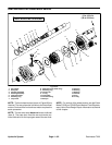
For cartridge valve service procedures, see Control
Manifold Cartridge Valve Service in this section. Refer
to Figure 63 for Filtration/Charge Control Manifold car-
tridge valve and plug installation torque.