


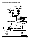
Reelmaster 7000 Hydraulic SystemPage 4 -- 55
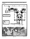
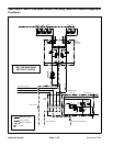
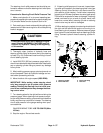
The gear pump P1 and P2 flow tests should be per-
formed to make sure that the mow circuits have ade-
quate hydraulic flow.
NOTE: Gearpump P1supplies hydraulicflow tocutting
units 1, 4 and 5. Gear pump P2 supplies flow to cutting
units 2 and 3.
Procedure for Gear Pump P1 and P2 Flow Test
NOTE: Overaperiod oftime,the gearsandwear plates
in the gear pumpcan wear. A worn pump will by pass oil
andmake thepump lessefficient.Eventually, enoughoil
losswill occurtocausethe cuttingunitmotorsto stallun-
der heavy cutting conditions. Continued operation with
a worn, inefficient pump can generate excessive heat
and cause damage to the seals and other components
in the hydraulic system.
1. Make sure hydraulic oil is at normal operating tem-
peraturebyoperatingthemachineforapproximatelyten
(10) minutes. Make sure the hydraulic tank is full.
2. Parkmachine onalevel surfacewith thecuttingunits
lowered and off. Make sure engine is offand the parking
brake is engaged.
3. Raise and support hood to allow access to pumpas-
sembly.
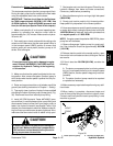
CAUTION
Prevent personal injury and/or damage to equip-
ment. Read all WARNINGS, CAUTIONS and Pre-
cautions for Hydraulic Testing at the beginning
of this section.
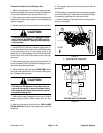
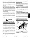
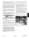
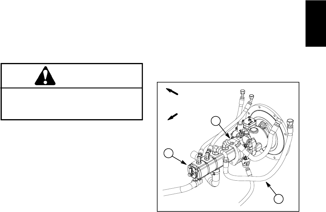
4. Locate gear pump section to be tested (P1 or P2).
Thoroughly cleanjunction ofappropriate hydraulichose
and gear pump fitting. Disconnect hydraulic hose from
hydraulic fitting in gear pump (Fig. 42).
IMPORTANT: Make sure that the oil flow indicator
arrow on the tester is showing that the oil will flow
from the gear pump fitting, through the tester and
into the disconnected hose.
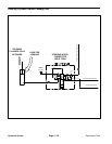
5. Install tester with pressure gauge and flow meter in
series with the disconnected hose and fitting in gear
pump section. Make sure the flow control valve on
the tester is fully open.
6. After installing tester, start engine andrun at low idle
speed. Check for hydraulic leakage and correct before
proceeding with test.
7. Move throttle to high idle speed (2850 RPM). Do not
engage the cutting units.
IMPORTANT: Do not fully restrict oil flow through
tester. In this test, the flow tester is positioned be-
fore thecircuit relief valve.Pump damage canoccur
if the oil flow is fully restricted.
8. Watch tester pressure gauge carefully while slowly
closing the flow control valve on tester until 2000 PSI
(138 bar) is obtained.Verify with a phototac thatthe en-
gine speed is 2850 RPM.
9. For a pump in good condition, flow indication should
be approximately 12 GPM (45.4 LPM).
10.Fully open flow control valve on tester and then shut
engine off. Record test results.
11.If measured flow is less than 10.8 GPM (40.8 LPM)
or a pressureof 2000 PSI (138bar) cannot be obtained,
check for restrictionin the pump intake line (including oil
filter and oil cooler). If line is not restricted, remove gear
pump and repair or replace as necessary.
12.After testing is complete, disconnect tester from hy-
draulic hose and fitting. Connect hoseto the gear pump
fitting.
13.Repeat test for second pump section if required.
14.Lower and secure hood after testing is completed.
1. Gear pump
2. Pump section P1 hose
3. Pump section P2 hose
Figure 42
FRONT
RIGHT
1
3
2
Hydraulic
System