


Reelmaster 7000 Page 7 -- 11 Chassis
CAUTION
Be careful when removing tension from the tor-
sion springon the rearlift arms. Thespring is un-
der heavy load and may cause personal injury.
4. Removetensionfromtorsionspringon rearofliftarm
tube (Fig. 11):
A. Insert nut driver or small piece of pipe onto the
end of the torsion spring that is on the rear of the lift
arm.
B. Push downand rearward onthe spring end toun-
hook the spring from the stop on the lift arm.
5. Loosen and remove lock nut (item 13) from lift arm
pivot pin.
6. Support lift arm and pull lift armpivot pin fromlift arm
and frame. Locate and remove thrust washer (item 16)
from rear of lift arm during pivot pin removal.
7. Remove lift arm and torsion spring from machine.
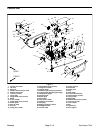
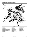
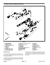
8. Disassemble lift arm as needed using Figure 9 as a
guide.
9. Clean lift arm and pivot pin. Inspect lift arm bushings
and pivotpin for damageor wear.Replace worn ordam-
aged components.
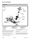
Installation (Fig. 9)
1. Assemble lift arm using Figure 7 as a guide.
2. Place torsion spring over rear of lift arm tube. Posi-
tion long leg of spring forward and pointing out from top
of spring.
3. Position lift arm to frame (Fig. 9). Fit thrust washer
(item 16) between rear of lift arm and frame. Slide pivot
pin into frame and lift arm. Align roll pin in pivot pin with
slot in frame flange.
4. Install and tightenlock nut (item 13) to secure liftarm
pivot pin.
5. Position lift cylinder rod clevis to lift arm
6. Make sure thatone (1) retaining ring and washer are
installed on cylinder pin (item 17). Insert cylinder pin
through the lift arm and lift cylinder clevis. Secure pin
with second washer and retaining ring. Make sure that
retaining ring is fully seated in pin.
CAUTION
Be careful when applying tension to t he torsion
spring on the rear lift arms. The spring is under
heavy load and may cause personal injury.
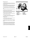
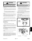
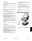
7. Apply tension to torsion spring (Fig. 11):
A. Insert nut driver or small piece of pipe onto the
longlegof thetorsionspringontherear oftheliftarm.
B. Pushdown andforward onthe springendto hook
the spring to the stop on the lift arm.
8. Positionand installcutting unitto liftarm (seeCutting
Unit Installation in the Service and Repairs section of
Chapter 8 -- DPA Cutting Units)
9. Lubricate lift arm andlift cylindergrease fittings after
assembly is complete.
10.After assembly, r aise and lower the cutting unit to
verify that hydraulic hoses and fittings do not contact
anything.
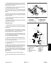
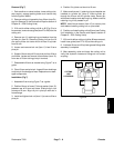
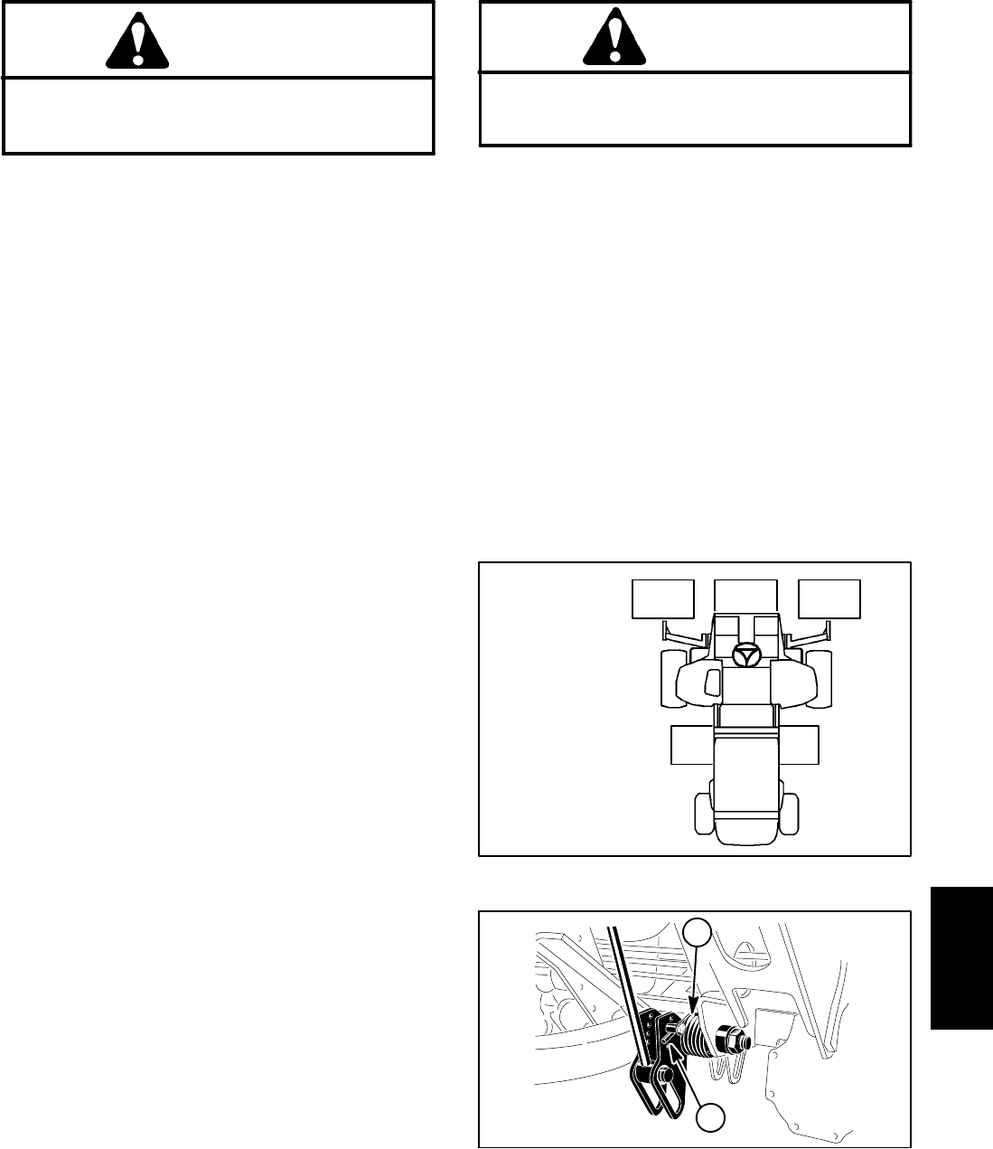
Figure 10
CUTTING
UNIT
LOCATIONS
#4 #1 #5
#2 #3
1. Torsion spring 2. Spring end
Figure 11
2
1
Chassis