


Reelmaster 7000 Hydraulic SystemPage 4 -- 119
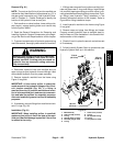
WARNING
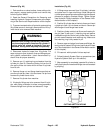
Make sure that cutting units are fully loweredbe-
fore loosening hydraulic lines from lift manifold.
If cutting units are raised as hydraulic lines are
loosened, cutting units may drop unexpectedly.
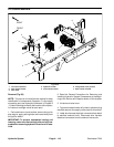
6. Disconnect hydraulic lines from manifold and put
caps or plugs on open hydraulic lines and fittings. Label
disconnected hydraulic lines for proper assembly.
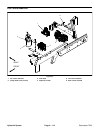
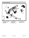
7. Remove hydraulic manifold from the frame using
Figure 88 as guide.
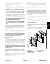
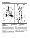
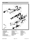
IMPORTANT: A flow control orifice is placed be-
neath hydraulic fittings in lift control manifold ports
C2, C3 and C4 (Fig. 89). If a fitting is removed from
thelift junctionmanifold andanorifice isin theman-
ifold port, make sure to remove orifice and label its
position for assembly purposes. Also note location
of groove in orifice for assembly purposes.
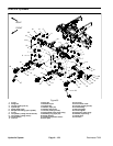
8. If hydraulic fittings are to be removed from lift c ontrol
manifold,mark fittingorientation toallow correctassem-
bly (Fig. 89). Remove fittings from manifold and discard
O--rings.
Installation (Fig. 88)
IMPORTANT: When installing orifice in manifold
port, make sure that orifice is flat in the base of the
manifold port. Manifold damage is possible if the
orifice is cocked in the cavity.
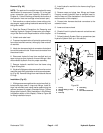
1. If fittings wereremoved from junction manifold, lubri-
cate and place new O--rings onto fittings. Install fittings
into manifold openings making sure that orifice is cor-
rectlyplacedbeforethreadingfittinginto manifold.Tight-
en fittings (see Hydraulic Fitting Installation in the
General Information section of this chapter). Refer to
Figure 89 for fitting installation torque.
2. Install hydraulic manifold to the frame using Figure
88 as guide.
3. Remove caps and plugs from fittings and hoses.
Properly connect hydraulic lines to manifold (see Hy-
draulic Hose and Tube Installation in the General Infor-
mation section of this chapter).
4. Connect wire harness electrical connectors to the
solenoid valve coils.
5. Lower and secure hood.
6. Check oil level in hydraulic reservoir and add correct
oil if necessary.
7. Follow Hydraulic System Start--up procedures (see
Hydraulic System Start--up in this section).
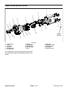
1. Lift manifold
2. Dust cap
3. Test fitting
4. O--ring
5. O--ring
6. Straight fitting (2 used)
7. O--ring
8. Orifice (0.040) (port C3)
9. Orifice (0.055) (port C4)
10. Orifice (0.109) (port C2)
11. O--ring
12. Straight fitting (4 used)
Figure 89
2
3
6
8
9
10
1
5
7
4
11
12
12
5
25 ft--lb
(34 N--m)
25 ft--lb
(34 N--m)
Hydraulic
System