


Reelmaster 7000
DPA Cutting Units
Page 8 -- 32
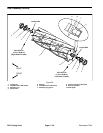
Front Roller
Removal (Fig. 34)
1. Positionmachine on a clean andlevel surface, lower
cutting units,stop engine, engage parkingbrake and re-
move key from the ignition switch.
2. Remove the cutting unitfrom the machineand place
on a level working surface. Use cutting unit kickstand
(see Special Tools) to raise front roller from work sur-
face.
3. Loosen flange nut and cap screw securing the front
roller shaft to each front height--of--cut (roller) bracket.
4. On one of the height --of--cut (roller) brackets:
A. Remove flange lock nut and carriage screw that
secure bracket to the cutting unit side plate.
B. Remove the height--of--cut (roller) bracket from
the cutting unit.
5. Slide the front roller assembly from the remaining
height--of--cut (roller) bracket on the cutting unit.
6. If necessary, remove the second height--of--cut (roll-
er) bracket from the cutting unit.
Installation (Fig. 34)
1. Place cutting unit on a level working surface and use
cutting unit kickstand (see Special Tools) to support cut-
ting unit.
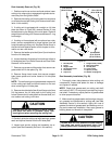
2. Inspect c ondition of cap screws (item 1) in both
height--of--cut (roller) brackets. Replace cap screw(s) if
necessary:
A. Place two (2) flat washers on cap screw and
thread flange lock nut onto cap screw to a position
0.750” (19 mm) from screw head.
B. Apply antiseize lubricant to cap screw threads
that will extend into height--of--cut (roller) bracket.
C. Thread cap screw into height--of--cut (roller)
bracket.
NOTE: When assembling height--of--cut (roller) brack-
etstosideplate,make surethatcapscrewheadandone
washer are above adjustment flange on side plate and
second washer and flange lock nut are below flange.
3. If both front height--of--cut (roller) brackets were re-
moved from cutting unit side plate, position one of the
brackets to side plate. Secure bracket to side plate with
carriage screw and flange lock nut.
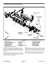
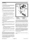
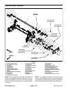
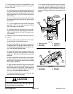
1. Cap screw
2. Flat washer
3. Flange lock nut
4. HOC (roller) bracket
5. Carriage screw
6. Cap screw
7. Flange nut
8. Front roller assembly
Figure 34
1
2
3
4
5
6
7
8
15 to 19 ft--lb
(20to26N--m)
Antiseize
Lubricant
Loctite #242
Loctite #242
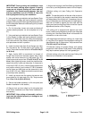
4. Slide front roller shaft into bracket attached to the
cutting unit. Slide second height--of--cut (roller) bracket
ontothe otherend ofroller shaft.Securesecond bracket
to cutting unit side plate with carriage screw and flange
nut.
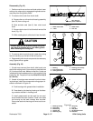
5. Apply Loctite #242 (or equivalent) to exposed
threads of cap screw (item 1) between flange of side
plate and position of flange lock nut (item 3) on cap
screw. Tighten flange lock nut on cap screw and then
loosennut 1/4to1/2 turn.Capscrewshould rotatefreely
with little (if any) endplay after lock nut installation.
6. Apply Loctite #242 (or equivalent) to threads of two
(2) cap screws (item 6). Center front roller to the cutting
reel and secure roller in place with two (2) cap screws.
Torque cap screws from 15 to 19 ft--lb (20 to 26 N--m).
Secure cap screws with flange nuts.
7. Lubricate front roller.
8. Adjust cutting unit (see Cutting Unit Operator’s
Manual).