


Reelmaster 7000Page 5 -- 22Electrical System
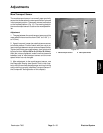
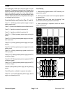
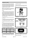
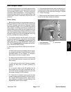
Cutting Unit Lift Switch
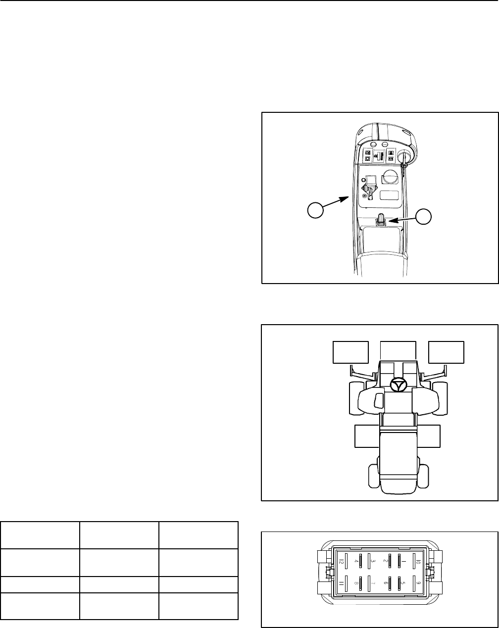
The cuttingunit lift switchis used as aninput for theTEC
controller to raiseor lower the cutting units. When thelift
switch paddle is depressed and held, the cutting units
will lower.When the lift switch paddle is raised and held,
the cutting units will raise. The cutting units will remain
in position when the switch is r eleased. The lift switch is
located on the console arm (Fig. 25).
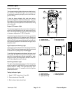
NOTE: Tolower thecutting units,themow speedlimiter
hasto beinmowrange (4WD).Also,toraise orlowerthe
cutting units, the seat has to be occupied.
Testing
1. Before disconnecting the lift switch for testing, the
switch and its circuit wiring should be tested as a TEC
input with the Diagnostic Display (see Diagnostic Dis-
playintheTroubleshootingsectionofthischapter).Ifthe
Diagnostic Display verifies that the lift switch and circuit
wiring are functioningcorrectly,no further switch testing
is necessary. If, however, the Display determines that
the lift switch and circuit wiring are not functioning cor-
rectly, proceed with test.
2. Make sure ignition switch is OFF. Remove key from
ignition switch.
3. Disassemble console arm to gain access to cutting
unitliftswitch(see ConsoleArmDisassemblyintheSer-
vice and Repairs section of Chapter 7 -- Chassis).
4. Disconnect harness electricalconnector from the lift
switch.
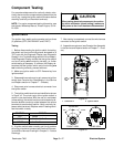
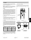
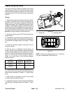
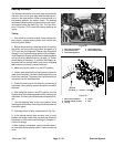
5. The switch terminals are marked asshown in Figure
27. Thec ircuit logic of thelift switch is shown inthe chart
below. With the use of a multimeter (ohms setting), the
switch functions may be tested to determine whether
continuity exists between the various terminals for each
position.Verifycontinuity betweenswitch terminals.Re-
place switch if testing identifies a faulty switch.
SWITCH
POSITION
CLOSED
CIRCUITS
OPEN
CIRCUITS
LOWER 2+1
6+5
2+4
6+8
NEUTRAL NONE ALL
RAISE 2+4
6+8
2+1
6+5
6. Iflift switch testscorrectly andcircuit problem stillex-
ists, check wire harness (see ElectricalSchematics and
Wire Harness Drawings in Chapter 9 -- Foldout Draw-
ings).
7. After testing is completed, connect wire harness
connector to the lift switch.
8. Assemble console arm (see Console Arm Assembly
in the Service and Repairssection of Chapter 7 -- C has-
sis).
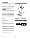
1. Console arm 2. Lift switch
Figure 25
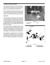
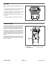
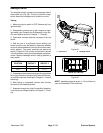
1
2
Figure 26
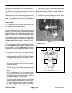
#4 #1 #5
#3#2
CUTTING
UNIT
LOCATIONS
Figure 27
BACK OF SWITCH
NOTE: Lift switch terminals 5, 6 and 8 are not used on
Reelmaster 7000 machines.