


Reelmaster 7000Page 3 -- 14Kubota Diesel Engine
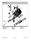
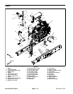
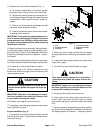
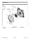
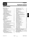
11.Remove fan motor and fan assembly (Fig. 11).
A. To prevent contamination of hydraulic system,
thoroughly clean exterior of fan motor and fittings.
B. Disconnect hydraulic hoses from cooling fan mo-
tor.Put capsor plugs onfittings andhoses to prevent
contamination. Label hydraulic lines for proper as-
sembly.
C. Remove six (6) cap screws and flange nuts that
secure fan motor bracket to radiator.
D. Carefullyremove fan motor,fanand motor brack-
et assembly from machine.
IMPORTANT: The hydraulic pumpassembly canre-
main in machine during engine removal. To prevent
pump assembly from shifting or falling, make sure
to support pump assembly before pump mounting
fasteners are removed.
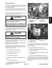
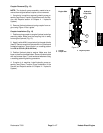
12.Support hydraulic pump assembly. Remove fasten-
ers that secure piston (traction) pump assembly to en-
gine (see Piston (Traction) PumpAssembly Removalin
the Service and Repairs section of Chapter 4 -- Hydrau-
lic System).
13.Make sure all cable ties securing the wiring harness,
fuel lines or hydraulic hoses to the engine are removed.
14.Connect lift or hoist to the lift tabs on engine.
15.Remove flange nuts, rebound washers and cap
screws that secure the engine mount brackets to the
rubber engine mounts.
CAUTION
One person should operate lift or hoist while a
second person guides the engine out of the ma-
chine.
IMPORTANT: Make sure to not damage the engine,
fuel lines, hydraulic lines, electrical harness or oth-
er parts while removing the engine.
16.Carefully raise engine from the machine.
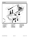
17.If necessary, removeengine mountsfrom theengine
using Figure 8 as a guide.
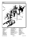
Engine Installation (Fig. 8)
1. Locate machineon a level surface with key removed
from the ignition switch. Chock wheels to keep the ma-
chine from moving.
Figure 11
1
2
3
4
5
6
1. Fan
2. Fan motor bracket
3. Fan motor
4. Cap screw (6 used)
5. Flange nut (6 used)
6. Radiator
2. Make sure that all parts removed from the engine
during maintenance orrebuilding are installedto the en-
gine.
3. Ifremoved, installengine mountsto theengineusing
Figure 8 as a guide.
4. Connect lift or hoist to the lift tabs on engine.
CAUTION
One person should operate lift or hoist while a
second person guides the engine into the ma-
chine.
IMPORTANT: Make sure to not damage the engine,
fuel lines, hydraulic lines, electrical harness or oth-
er parts while installing the engine.
5. Carefully lower engine into the machine.
6. Align engine to the rubber engine mounts and hy-
draulic pump input shaft. Secure engine to engine
mounts with cap screws, rebound washers and flange
nuts.
7. Securehydraulicpump assemblytoengine(seePis-
ton(Traction)PumpAssembly InstallationintheService
and Repairs section of Chapter 4 -- Hydraulic System).