


Reelmaster 7000 Page 7 -- 13 Chassis
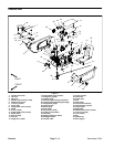
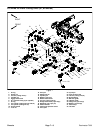
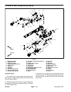
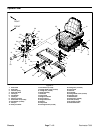
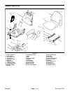
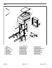
Removal (Fig. 12)
1. Park machine on a level surface, lower cutting units,
stop engine, apply parking brake and remove key from
the ignition switch.
2. Disconnect seat electrical connector from machine
wire harness.
3. Support console arm assembly to prevent it from
shifting.
4. Remove flange nut (item 25) and carriage screw
(item 24) that secure support bracket (item 21) to sup-
port channel (item 19).
5. Remove cap screw (item 26) that secures console
arm support (item 20) to hex nut (item 27).
6. Remove cap screw (item 23), flat washer (item 10),
spacer(item 22)and seatbeltbuckle (item35) fromseat
and console arm support (item 20).
IMPORTANT: Make sure to not damage the electri-
cal harness, control cable or otherparts while mov-
ing the console arm assembly.
7. Carefully move console arm assembly away from
seat. Support console arm to prevent it from falling.
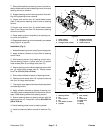
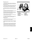
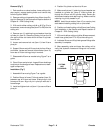
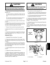
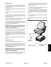
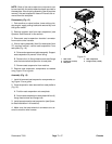
8. Remove four (4) torx head screws that secure seat
to seat suspension (Fig. 13). Note that the screw near
theseatadjustmenthandle islongerthanthe otherthree
(3) screws.
9. Lift seat from seat suspension andremove fromma-
chine.
Installation (Fig. 12)
1. Carefully position seat to seat suspension.
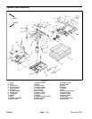
2. Secure seat to seat suspension with four (4) torx
head screws (Fig. 13). Make sure that longer screw is
positioned near the seat adjustment handle. Torque
screws 18 ft--lb (25 N--m).
IMPORTANT: Make sure to not damage the electri-
cal harness, control cable or otherparts while mov-
ing the console arm assembly.
3. Position and secure console arm assembly to seat.
Install all fasteners before fully tightening them.
A. Secure support bracket (item 21) and support
channel (item 19) with flange nut (item 25) and car-
riage screw (item 24).
B. Secure console arm support (item 20) to hex nut
(item 27) with cap screw (item 26).
C. Placeflat washer (item 10), seatbelt buckle (item
35) and spacer (item 22) between seat and console
arm support (item 20). Secure w ith cap screw (item
23).
D. Fully tighten all fasteners to secure console arm
assembly to seat.
4. Connect seat electrical connector to machine wire
harness.
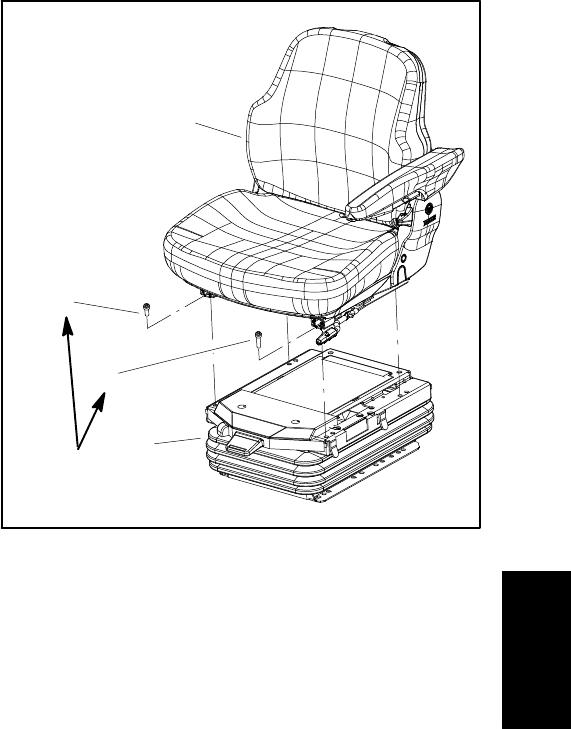
1. Seat
2. Suspension assembly
3. Screw (M8x12) (3 used)
4. Screw (M8x16)
Figure 13
2
3
1
4
18 ft--lb
(25 N--m)
Chassis