Reelmaster 7000
DPA Cutting Units
Page 8 -- 15
Cutting Unit Removal and Installation
Cutting Unit Removal
1. Park machine on a clean and level surface, lower
cutting units completely to the ground, stop engine, en-
gage parking brake and remove key from the ignition
switch.
2. If front outside cutting units (#4 or #5 cutting unit) is
being removed, separate hydraulic hoses from hose
guide.
3. Remove hydraulic reel motor from cutting unit that is
to be removed (see Hydraulic Reel Motor Removal in
this section). Position motor away from cutting unit.
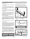
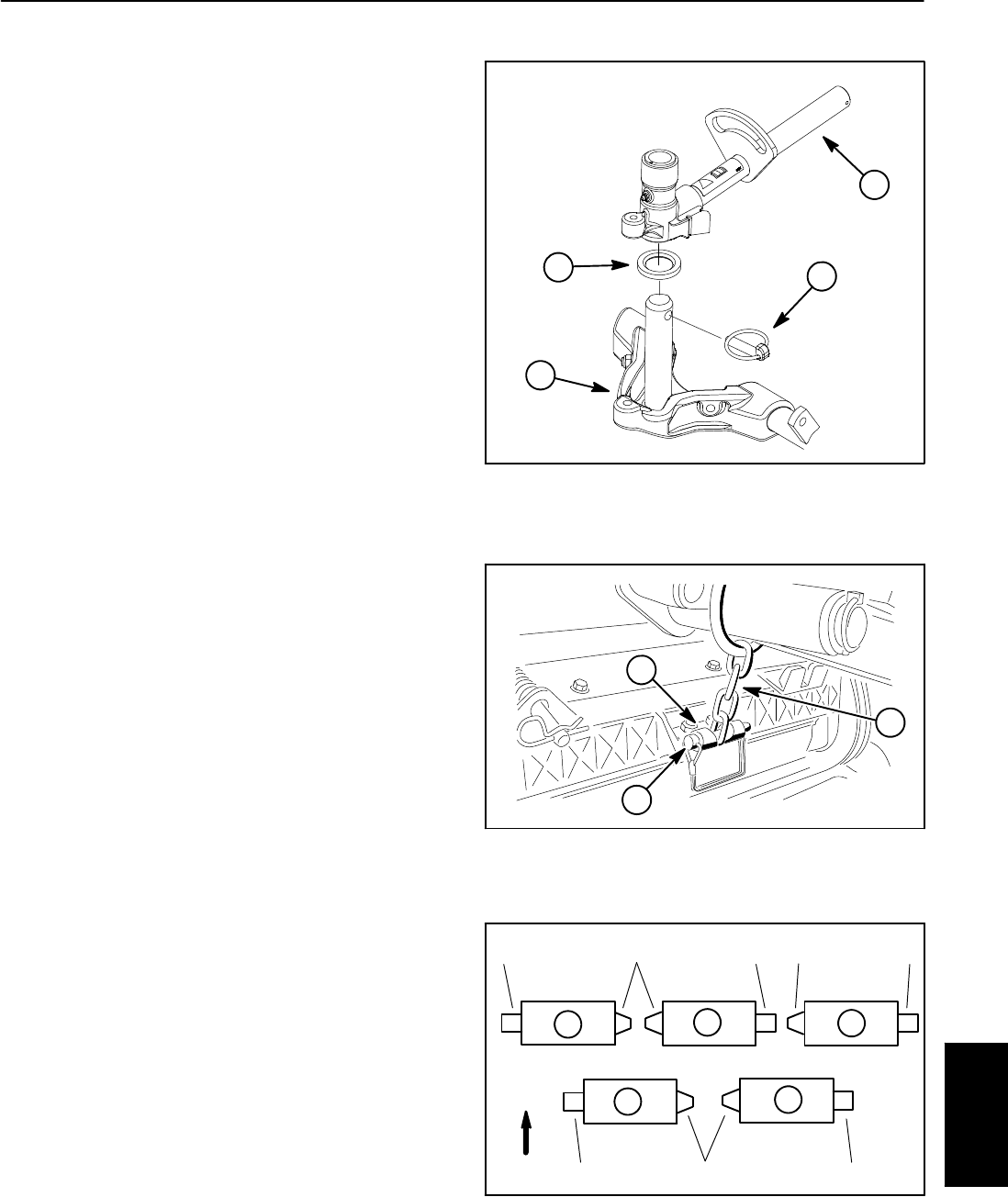
4. Remove snapper pin from cutting unit chain bracket
and lift arm chain (Fig. 17).
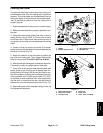
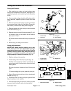
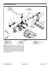
5. Removecutting unit fromlift armpivot yoke (Fig.16):
A. Remove lynch pin that retains carrier frame to
pivot yoke in lift arm.
B. Remove carrierframe shaft from pivotyoke on lift
arm.
6. Move cutting unit away from machine.
Cutting Unit Installation
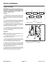
IMPORTANT: When installing cutting unit to ma-
chine, make sure that turf compensator spring is
mounted on the same side of the cutting unit as the
hydraulic reel drive motor. Also, make sure that cut-
ting unit is installed on machine with motor and
weight properly orientated to machine (Fig. 18).
1. Position cutting unit to machine.
2. Install cutting unit to lift arm pivot yoke (Fig. 16):
A. Make sure that thrust washer is positioned on
carrier frame shaft. Coat the carrier frame shaft with
clean grease.
B. Insert the carrier frame shaft into lift arm pivot
yoke.
C. Secure cutting unit to pivot yoke with lynch pin.
3. Secureliftarmchain tocuttingunitchainbracketw ith
snapper pin (Fig. 17).
4. Install reel motor to cutting unit (see Hydraulic Reel
Motor Installation in this section).
5. If front outside cutting unit (#4 or #5cutting unit) was
removed, install hydraulic hoses into hose guide.
1. Carrier frame
2. Lynch pin
3. Pivot yoke
4. Thrust washer
Figure 16
2
1
4
3
1. Lift arm chain
2. Chain bracket
3. Snapper pin
Figure 17
2
1
3
1. Reel motor location 2. Weight location
Figure 18
FRONT
3
4
5
1
2
1
2
2
1 1
2 11
DPA Cutting
Units


