


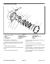

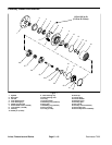
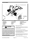
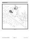
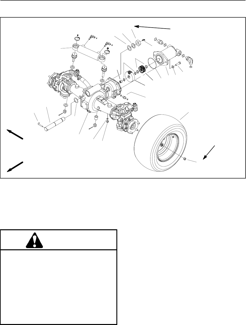
Reelmaster 7000Page 6 -- 14Axles, Planetaries and Brakes
Rear Axle Assembly
1. Steering cylinder
2. Needle bearing
3. External snap ring
4. External snap ring
5. Thrust washer
6. Flat washer
7. Lock nut
8. Grease fitting
9. Cap screw (2 used)
10. Flat washer (2 used)
11. Rear axle motor
12. O--ring
13. Pinion gear
14. Gear
15. Stop pin
16. Hydraulic fitting
17. Rear wheel assembly (2 used)
18. Lug nut (5 used per wheel)
19. Hex plug
20. O--ring
21. Drive axle assembly
22. Axle pivot pin
Figure 9
70 ft--lb (94 N--m) maximum
FRONT
RIGHT
1
2
3
13
4
14
12
9
10
11
17
21
20
19
18
22
5
6
8
7
16
15
85 to 100 ft--lb
(116 to 135 N--m)
5
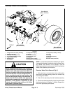
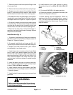
CAUTION
When changing attachments, tires or perform-
ingother service,use correct blocks,hoists and
jacks to raise and support machine. Make sure
machine is parked on a solid level surface such
as a concrete floor. Prior to raising machine, re-
move any attachments that may interfere with
the safe and proper raising of the machine. Al-
ways chock or block wheels. Use appropriate
jack stands to supportthe raised machine. If the
machine is not properly supported by jack
stands, the machine may move or fall, which
may result in personal injury.
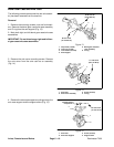
Remove Rear Axle (Fig. 9)
1. Park machine on a level surface, lower cutting units,
stop engine, engage parking brake and remove key
from the ignition switch.
2. Drain oil from rear axle and axle gearbox.
3. Chockfront wheels and jack up rearof machine (see
JackingInstructions inChapter 1 -- Safety).Supportma-
chine with appropriate jack stands.
4. Remove both w heels from rear axle.
5. Remove hydraulic motor from axle assembly (see
Rear Axle Motor in the Service and Repairs section of
Chapter 4 -- Hydraulic System).
6. Remove hydraulic hoses from steering cylinder.