


Operating Basics: User Interface
2-28 OTS9100 User Manual
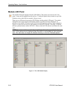
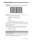
Signal Structure
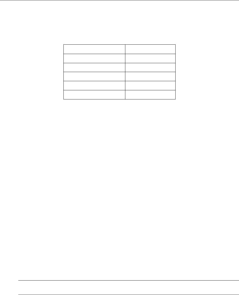
Signal structure allows the user to choose the mapping structure of the transmitted signal. The
mapping structures provided are listed in the table below. As shown, the structures all provide
concatenated structures.
SONET SDH
1 x STS-192c 1 x VC4-64c
4 x STS-48c 4 x VC4-16c
16 x STS-12c 16 x VC4-4c
64 x STS-3c 64 x VC4
192 x STS-1 192 x VC3
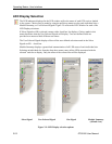
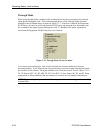
Test Pattern
Test Pattern allows the user the select a pattern to fill the chosen active channel of the internally
generated 9.95238 Gb/s signal. The patterns available are:
PN15 (PRBS 2^15-1), Inverted PN15 (ITU O.151)
PN23 (PRBS 2^23-1), Inverted PN23 (ITU O.151)
PN31 (PRBS 2^31-1), Inverted PN31 (ITU O.150)
All Zeros
All Ones
Fixed Data (8-bit)
POS (Only valid when Signal Structure is STS-192c/VC-4-64C)
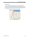
When Fixed Data is selected a button marked Edit Fixed Data is displayed. To change the Fixed
Data to a different value, click the Edit Fixed Data button and type the new value into the text
box beside the button. In the Test Pattern selection box, observe that the value after Fixed Data
changes to match the newly entered value.
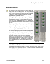
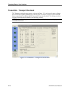
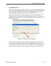
Packet Over SONET (POS)
In order to use the POS testing capabilities, POS must be selected as the Active Channel Test
Pattern. Select POS from the drop down menu under Active Channel Test Pattern in the
Receiver Setup menu. The following setup conditions must exist before POS can be selected:
• Signal Source is set to Internal.
• Timing Source is set to Internal.
• Signal Structure is set to STS-192c.
NOTE: To transmit a POS test pattern, the Signal Structure must be set to STS-192c and the
signal source cannot be through mode.
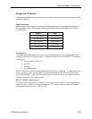
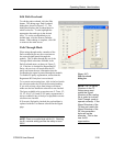
SPE/VC3 Stuff Column Control
The stuff column control allows column 30 and column 59 of the SPE (VC3) to be stuffed with
either all zeros or with the payload pattern. This option is only available if the Signal Structure
is STS-1 or VC3.
Set channel from 1 to 192 or set all.