Operating Basics: User Interface
2-18 OTS9100 User Manual
LED Window
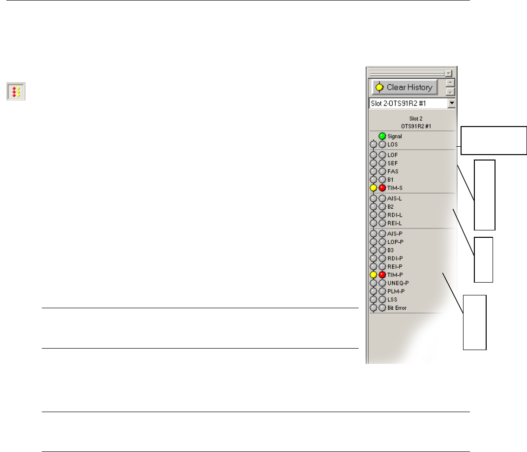
Activating the LED Status window provides the user with a virtual
LED status panel for the OTS9100 receiver(s), as shown in
Figure 2-7. The virtual indicators found on this window
provide error conditions, both current and historical, for
all traditional receiver error LEDs. The LED Status window
may be activated through the View menu or from the toggle key
on the toolbar.
Each condition has two separate indicators, the one on the right
is the Current condition and the indicator on the left is the
History. The Current indicators will turn red and the History
indicators will turn yellow if an error condition currently exists.
Once the condition has been removed, the red Current indicator
will turn off. The yellow History indicator will remain on until a
new test has been started or until the Clear History button is clicked.
See Table 2-1 for a description of each indicator.
Note: Extended Panel information can be viewed with
scrolling LED bars, this feature is only enabled when a panel
is extended beyond the framework.
Three LED panel views can be enabled from within the OTS9000
application, the Module Summary Panel, the Slot Signal Panel and
the User Customizable Signal Panel.
Note: The LED panels display Receiver information only.
When only one receiver has been selected from the navigation
bar no user selectable signals will be available.
Click on the drop down menu for the LED panel to access the possible choices for the LED
panel. Each selection provides specific controls for the active LED. The choices are Module
Signal, Slot Signal and User Selected Signal. Each state is described below.
S
E
C
T
I
O
N
I
P
A
T
H
AGGREGATE
SIGNAL
