


Operating Basics: Functional Overview
OTS-9100 User Manual 2-3
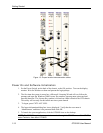
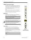
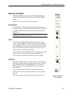
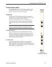
Optical IN
The Optical IN connection accepts the incoming optical signal to
the receiver. This input signal must have a wavelength between
1290 nm and 1565 nm and must not exceed –0 dBm of power.
The green LED labeled SIG PRES under the Optical IN heading
will light when the Optics card detects an incoming signal. Red
flashing indicates an optical loss condition. An amber flashing
LED indicates an optical overload condition.
WARNING: The incoming signal must be attenuated to within
specified power levels. If the signal exceeds –0 dBm, damage may
occur.
Rx DATA OUT
Rx DATA OUT provides signal interconnection between the
module cards. This output must be connected to the Rx DATA IN
connection found on the Receive card of the OTS9100 module
using the coax cable and DC block provided.
Rx DATA OUT
Rx DATA OUT is a 10 Gb/s DATA Signal provided for jitter
measurements. This signal must be connected to the 10 Gb/s
DATA IN connector of the OTS92H1 Clock Receive card.
Tx Data IN
Tx Data Input provides signal interconnection between the module
cards. This input must be connected to the Tx Data Out
connection found on the Transmit card of the OTS9100 module
using the coax cable provided.
WARNING: Always avoid exposure to the laser beam. Before power
is applied to the OTS9100 module be sure that all laser outputs
are either covered with the screw cap provided or connected to the
appropriate circuit.
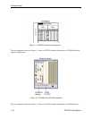
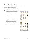
Figure 2-3:
1550 nm Transceiver
Front Panel