


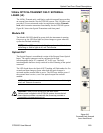

Optical Card Front Panel Descriptions
OTS9100 User Manual B-5
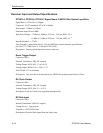
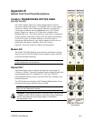
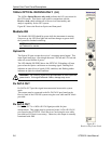
Tx Data IN
Tx Data Input allows electrical data signals to be applied to the optical
transmitter. This input must be connected to the Tx Data Out port found
on the OTS91Tn Transmitter card of the OTS9100 system using the
coax cable provided.
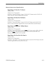
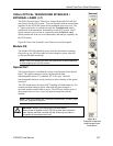
Laser Lockout, Remote Interlock
REMOTE INTERLOCK is a bantam plug normally closed connection
internally wired in series with the laser lockout key switch. It can be
used with additional hardware to disable the laser output.
NOTE: If this connection is used, the ferrite bead provided with the
module must be attached to the remote interlock cable for lower
emissions and CE mark conformance. Install the bead close to the
end of the cable connected to the Optics card.
Laser LOCKOUT is a safety device. The key switch disables the laser
output when it is turned to the “open lock” position. The laser output
can only be turned on when the key is in the “closed lock” position.
NOTE: The laser output cannot be enabled unless:
The Laser Lockout key switch is set to the “open lock” or on position.
The Remote Interlock is either not used or externally enabled.
The Laser output is software enabled.
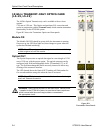
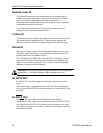
1. NOTE: Optical cables use and care. When using the optical
cables ensure that the cable is firmly seated in the front panel
connector. The optical connectors on the front panel are keyed.
If the cable is not inserted into the connector key properly, the
connection between cable and front panel will not be complete
and so will cause errors in transmission and receiver functions.
2. Always be sure to clean both cable connectors and front panel
connectors before installing optical cables. A dirty optical
connection can cause errors in transmission and receiver
functions.