


OTS9100 User Manual 2-1
Module Operating Basics
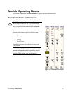
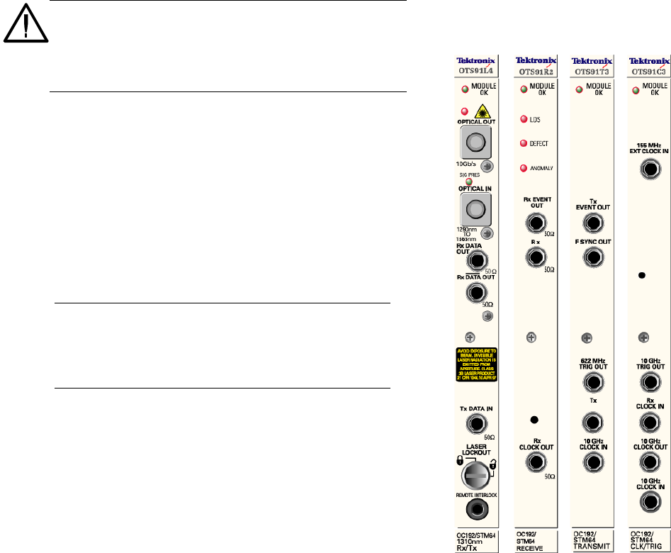
This section describes the OTS9100 module front panel indicators and connectors.
Front Panel Indicators and Connectors
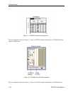
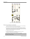
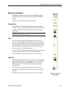
Figure 2-1 shows a complete view of the front panel.
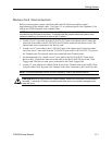
WARNING: Always avoid exposure to the laser beam.
Before power is applied to the OTS9100 module be
sure that all laser outputs are either covered with the
screw cap provided or connected to the appropriate
circuit.
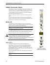
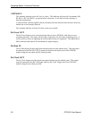
The front panel is made up of four different cards:
• Optics
• Transmit
• Receive
• Clock Trigger
The following sections describe each of these cards
in more detail.
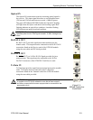
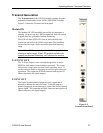
NOTE: There are several versions of the optical card
available. Each OTS91Lx series card has been
designed with targeted analysis capabilities directed
at specific analysis needs. For additional information
on each OTS91Lx series card see Appendix A.
Figure 2-1: OTS9100 Front Panel