


Optical Card Front Panel Descriptions
2-8 OTS9100 User Manual
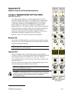
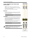
External Laser IN
The External Laser In provides interconnection for external fixed or
tunable wavelength laser sources. The input will accept OTS Tunable
lasers or customer supplied lasers that meet specifications. A
polarization-maintaining (PM) jumper and an optical source with good
polarization extinction are required.
As with the Optical Output, the Tx optical input connector can be
configured with field interchangeable shells.
Tx Data IN
Tx Data Input provides signal interconnection between the system cards.
This input must be connected to the Tx Data Out port found on the
Transmit card of the OTS9100 system using the coax cable provided.
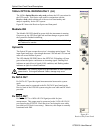
Optical IN
The Optical IN port accepts the incoming optical signal to the receiver.
This input signal must have a wavelength between 1290 nm and 1565
nm and must not exceed 0dBm of power.
The LED labeled SIG PRES above the OPTICAL IN heading will turn
green when the Optics card detects an incoming signal. Flashing Red
indicates an optical loss of signal (LOS) condition, and flashing amber
indicates an optical overload condition.
WARNING: The incoming signal must be attenuated to within specified
power levels. If the signal exceeds 0 dBm, damage may occur.
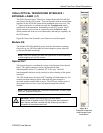
Rx DATA OUT
Rx DATA OUT provides signal interconnection between the system
cards.
This output must be connected to the Rx DATA IN port found on the
Receive card of the OTS9100 system using the coax cable and DC block
provided.
Rx DATA OUT
Rx DATA OUT is a 10Gb/s DATA Signal provided for jitter
measurement. This output must be connected to the 10 Gb/s DATA IN
port found on the OTS92H1 Clock Receiver Card using the coax cable
provided (no DC block is necessary). Otherwise, this output is normally
terminated with 50Ω.