TP-6200 10/12 49Section 2 Operation
D Fixed Voltage when entry is beyond the range of
limited entries for the respective alternator. Occurs
when the alternator is not rated for the value entered.
Updated parameter files may be available by
contacting an authorized service dealer/distributor.
Func (Function) Used by (RDO) XX Reassign?
appears when the user attempts to assign an RDO to a
function already assigned.
Internal Error appears when controller logic detects a
functional sequence error.
Invalid Code appears when the user attempts to enter:
D An invalid access code for programming mode setup,
or
D An invalid access code for setup unlock.
Invalid Menu ID appears when the user attempts to
enter a menu number that is unavailable or non-
functional.
N/A appears when data to be displayed is not available.
No Input Assigned appears when the user attempts to
assign any of the following system faults to an RDO
where the digital input is not defined. See digital input
scale requirements in Menu 12—Calibration.
D Air damper indicator
D Battery charger fault
D Ground fault
D High oil temperature shutdown
D Low coolant level
D Low fuel
Not in Local Program Mode appears when the user
attempts to program using the keypad when the
programming mode is set for remote or off.
Not User-Selectable appears when the user attempts
to change an analog or digital input that is factory-
reserved. Items identified as not user-selectable are
included for specific applications. (Example: AFM
SHUTDOWN is enabled with a Waukesha-powered
model.) The user cannot disable an analog or digital
input when identified as not user-selectable. See
Figure 2-8 in User Inputs for factory-reserved digital
and analog inputs that are not user-selectable.
Output in Use appears when the user attempts to
modify or reassign an active RDO.
Port in Use appears when the user attempts to use an
already assigned communications port.
Range Error appears when the user attempts to enter:
D A numeric input that is not within the acceptable range
of the system settings, time delays, addresses, etc.
D An invalid analog or digital input number.
D An invalid date/time.
Remove Load appears when trying to calibrate the
voltage regulator in menu 12 with load connection. The
voltage regulation calibration must be performed during
a no load condition.
Setpoint Values Cannot be Equal appears when the
user attempts to enter the same value for both setpoints
during the analog input calibration.
2.6 Monitoring and Programming
Setup
The user can access the controller data with the
controller keypad and display or a personal computer
(PC) with optional software to monitor and/or program.
Access the controller system with a PC using local
(direct) or remote (modem) systems. Refer to the
Introduction, List of Related Materials for related
software literature. See Menu 13—Communications.
The user can access the controller data while in the
programming mode off or programming mode on. See
Menu 14—Programming Mode.
While this manual focuses on data access and
programming through the controller keypad and display,
some data entries require input using a PC for initial
setup. The PC entries typically include alpha characters
such as digital input descriptions. The individual menus
in Section 2.8, Local Programming Mode On, indicate
where data requires entry using a PC.
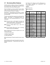
There are six basic configurations for data monitoring
and programming using access source options. See
Figure 2-13.
Other combinations of data monitoring and
programming are possible but require programming
from a single location. Figure 2-13, Monitoring and
Programming Configurations, briefly describes the
settings of Menu 13—Communications and Menu 14—
Programming Mode based on user-selected operating
mode.
Use the keypad and digital display to setup the access
configurations the first time. Go to Section 2.8, Local
Programming Mode On, and set the desired
selection in Menu 13—Communication and Menu 14—
Programming Mode before accessing data.


