TP-6200 10/12 45Section 2 Operation
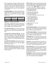
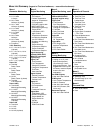
Menu List Summary, continued (Legend: D First level submenu, d second level submenu)
Menu 11
Voltage Regulator
Group B, continued
Reverse Power Shutdown[
Over Power Shutdown[
Loss of Field Shutdown[
Overcurrent VR Shutdown[
Common Protective Relay
Output[
In Synchronization[
Breaker Trip[
Fuel Valve Relay*
Prelube Relay*
Air/Fuel Module Remote
Start*
No Oil Temperature Signal*
High Oil Temperature
Warning*
]
No Air Temperature Signal*
Intake Air Temperature
Warning*
]
Intake Air Temperature
Shutdown*
]
Air/Fuel Module Engine
Start Delay*
ECM Yellow Alarm
]
ECM Red Alarm]
Block Heater Control]
Low Coolant Temperature
Shutdown]
Load Shed
Overtemperature
]
Maintenance Due
Engine Derate Active
Engine Stalled
(ECM engines)
J1939 CAN Shutdown
(ECM engines)
*Waukesha engine
[Paralleling applications
]DDC/MTU engine with
MDEC/ADEC
AVG L-L V
Volt ADJ
D L1-L2 Volts
D L2-L3 Volts (3 phase)
D L3-L1 Volts (3 phase)
Under Freq. Unload
Enabled N/Y
D Frequency
Setpoint (Cut-In Point)
D Slope
Volts-Per-Cycle
Reactive Droop
Enabled N/Y
D Voltage Droop at 0.8 P F
Rated Load
VAR Control
Enabled N/Y
D Total kVAR (Running)
kVAR Adj
D Generating/Absorbing Y/N
PF Control
Enabled N/Y
D Average PF
PF Adjustment
D Lagging/Leading Y/N
Regulator Gain Adj.
D Gain
Utility Gain Adj.
D Gain
Analog Voltage Adjust
Enabled N/Y
Reset Regulator Defaults?
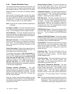
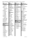
Menu 10
Output Setup, cont.
Group B, continued
Low Battery Voltage
High Battery Voltage
Battery Charger Fault
System Ready
Loss of ECM Comm
(ECM engines)
No Oil Pressure Signal
High Oil Temperature
Shutdown
No Temperature Signal
Low Coolant Level
Speed Sensor Fault
Locked Rotor
Master Switch Error
Master Switch Open
Master Switch to Off
AC Sensing Loss
Over Voltage
Under Voltage
Weak Battery
Over Frequency
Under Frequency
Load Shed kW Over
Load Shed Under Freq
Over Current
EPS Supplying Load
Internal Fault
Delay Engine Cooldown
Delay Engine Start
Starting Aid
Generator Set Running
Air Damper Control
Ground Fault
EEPROM Write Failure
Critical Overvoltage
Alternator Protection
Air Damper Indicator
Defined Common Fault
(RDO only)
SCRDOs 1--4 (Software-
Controlled RDOs)
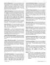
Menu 10
Output Setup, cont.
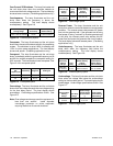
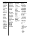
Menu 12
Calibration
Scale AC Analog
Inputs
Generator Set Voltage LN
D Gen L1-L0 V
Calibration Reference
D Gen L2-L0 V
Calibration Reference
D Gen L3-L0 V (3 phase)
Calibration Reference
Generator Set Voltage LL
D Gen L1-L2 V
Calibration Reference
D Gen L2-L3 V (3 phase)
Calibration Reference
D Gen L3-L1 V (3 phase)
Calibration Reference
D Calibrate Regulator Y/N
Generator Set Amps
D Gen L1 Amps
Calibration Reference
D Gen L2 Amps
Calibration Reference
D Gen L3 Amps (3 phase)
Calibration Reference
Load Voltage LN
(Paralleling Applications
only)
D Load L1--L0 V
Calibration Reference
D Load L3--L0 V
Calibration Reference
Restore Defaults? Y/N
Scale Aux. Analog
Inputs
D Zero Aux. Analog
Inputs?
(Scroll through up to 7
user-defined
descriptions. See
Figure 2-8 in User Inputs
for factory-reserved
inputs that are not user-
selectable.)
D Analog 01
Scale Value 1
d Scale1V
Scale2V
D Analog 01
Scale Value 2
d Scale1V
Scale2V


