TP-6200 10/12 17Section 1 Specifications and Features
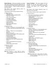
System Warning. Yellow lamp identifies an existing
fault condition that does not shut down the generator set.
A continuing system warning fault condition may cause
a system shutdown. Correct all system warnings as
soon as practical.
See Section 2.3.5, System Warning Lamp, for
definitions of the items listed.
The following conditions cause a system warning:
D Engine functions:
d ECM yellow alarm
(DDC/MTU engine with MDEC/ADEC)
d High battery voltage
d High coolant temperature
d Low battery voltage
d Low coolant temperature
d Low fuel (level or pressure)*
d Low oil pressure
d Speed sensor fault
d Starting aid (system status)
d Weak battery
D General functions:
d Auxiliary—Analog up to 7 user-selectable inputs
each with a high and low programmable warning
level
d Auxiliary—Digital up to 21 user-selectable
warnings
d Battery charger fault*
d Emergency power system (EPS) supplying load
d Engine cooldown delay
d Engine start delay
d Load shed kW overload
d Load shed underfrequency
d Master switch not in AUTO (automatic start)
position
d NFPA 110 fault (National Fire Protection
Association)
d System ready (system status)
D Alternator functions:
d AC sensing loss
d Ground fault*
d Overcurrent
* Requires optional input sensors.
Note: See Figure 2-8 in User Inputs for factory-
reserved analog and digital inputs that are not
user-selectable.
System Shutdown. Red lamp i ndicates that the
generator set has shut down because of a fault
condition. The unit will not start without resetting the
controller, see Section 2.3.7, Controller Reset
Procedure.
See Section 2.3.6, System Shutdown Lamp, for
definitions of the items listed.
The following conditions cause a system shutdown:
D Engine functions:
d Air damper closed (status), if equipped
d Coolant temperature signal loss
d ECM red alarm
(DDC/MTU engine with MDEC/ADEC)
d Engine stalled (ECM only)
d High coolant temperature
d High oil temperature
d Low coolant level
d Low oil pressure
d Oil pressure signal loss
d Overcrank
d Overspeed
D General functions:
d Auxiliary—Analog up to 7 user-selectable inputs
each with a high and low programmable
shutdown level
d Auxiliary—Digital up to 21 user-selectable
shutdowns
d ECM communications loss (ECM models only)
d Emergency stop
d Internal fault
d Master switch in OFF/RESET position
d Master switch error
d Master switch open
d NFPA 110 fault
D Alternator functions:
d AC output overvoltage
d AC output undervoltage
d Alternator protection against overload and short
circuits
d Field overvoltage
(M4, M5, M7, or M10 alternator only)
d Locked rotor (failed to crank)
d Overfrequency
d Underfrequency
Note: See Figure 2-8 in User Inputs for factory-
reserved analog and digital inputs which are
not user-selectable.


