TP-6200 10/12172 Section 6 Accessories
6.1.7 Low Fuel (Level/Pressure) Switch
Some gaseous-fueled models offer a low fuel pressure
switch. The low fuel pressure switch connects to the
same terminal as the low fuel level switch on diesel- or
gasoline-fueled models. See Figure 6-10 and
Figure 6-11. See Section 6.2, Accessory Connections,
for terminal identification.
Note: The main tank or the transfer/day tank includes
the low fuel level switch. The fuel tank supplier
typically provides the low fuel level switch.
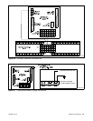
GM16088A-A
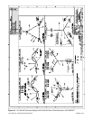
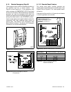
Figure 6-10 Low Fuel Switch (Level or Pressure)
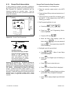
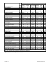
Switch Rating 12 volts DC minimum, 0.5 amp minimum
Wiring Recommendation
Gauge mm (ft.)
18--20 30.5 (100)
14 153 (500)
10 305 (1000)
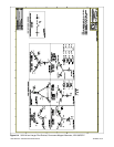
Figure 6-11 Switch Rating & Wiring Recommendation
6.1.8 Prime Power Switch Kit
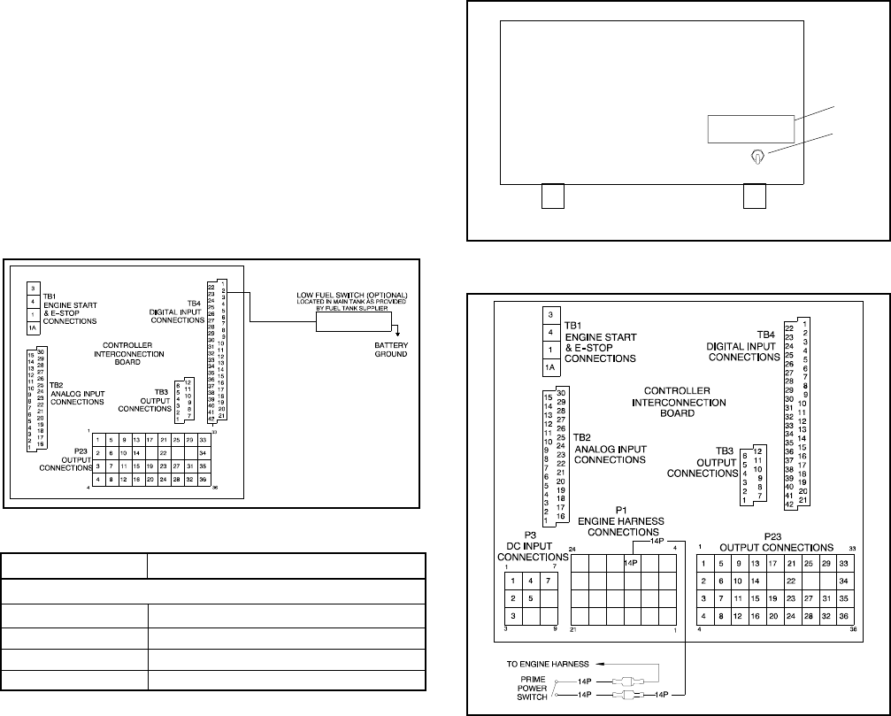
The prime power switch kit prevents battery drain during
generator set nonoperation periods and when the
generator set battery cannot be maintained by an AC
battery charger. See Figure 6-12 for an illustration of the
kit and Figure 6-13 for the electrical connections.
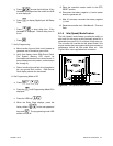
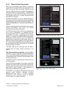
1. Prime power decal (293668)
PRIME POWER
SWITCH
GM20652-
1
2
2. Toggle switch (354464)
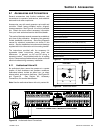
Figure 6-12 Prime Power Switch Installation Location
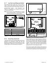
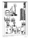
GM16088A-D
Toggle switch shown in
the prime power mode off
position (contacts open)
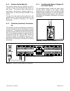
Figure 6-13 Prime Power Switch Connections
Stop the generator set using the stopping procedures in
Section 2.3.2, Stopping, before placing the generator
set in the prime power mode. Move the prime power
switch located on the back of the controller to the DOWN
position. The controller including the digital display,
LEDs, and alarm horn does not function when the
generator set is in the prime power mode.
Move the prime power switch located on the back of the
controller to the UP position and reset the controller time
and date before attempting to start the generator set.


