


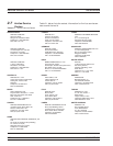

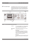
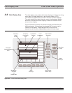
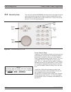

3-2 Front Panel Layout The MG369XB front panel is divided into two main areas—the data
display area and the data entry area. The following paragraphs pro
-
vide a brief description of the front panel controls and data display
and data entry areas as shown in Figure 3-1. Detailed descriptions of
the data display and data entry areas are contained in Sections 3-3
and 3-4.
Line Key
The line key provides for turning the signal genera
-
tor on and off. STANDBY (off) is indicated by an or
-
ange LED; OPERATE (on) by a green LED.
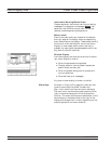
Data Display
Area
The data display area consists of the data display
and the surrounding menu keys.
Data Display
The data display provides information about the
current status of the MG369XB in a menu display
format. This information includes the operating
mode of the instrument and the value of the active
frequency and power level parameters.
Menu Keys
Menu keys provide for selecting the operating mode,
parameters, and configuration of the signal genera
-
tor.
3-6 MG369XB OM
Front Panel Layout Local (Front Panel) Operation
M o d u la tion
L ine
O p e ra te
S tan d b y
L e ve l
F re q u e nc y
S ys tem
O u tp ut
O n O ff
R F O u tpu t
5 0
9
C lea r
E ntry
B ac k
S pa c e
7 8 9
4 5 6
1 2 3
0
.
+ /-
D a t a D is p la y
D a t a E n t r y
R F O u t p u t
C o n n e c t o r
M e n u
K e y s
L in e
K e y
R F O u t p u t
C o n t r o l
K e y
Figure 3-1. Front Panel, MG369XB Synthesized Signal Generator