


2-5 GPIB Setup and
Interconnection
The MG369XB provides automated microwave signal generation via
the GPIB. The following paragraphs provide information about inter
-
face connections, cable requirements, setting the GPIB operating pa
-
rameters, and selecting the external interface language.
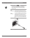
Interface
Connector
Interface between the signal generator and other de
-
vices on the GPIB is via a 24-wire interface cable.
This cable uses connector shells having two connec
-
tor faces. These double-faced connectors allow for
the parallel connection of two or more cables to a
single device.
Cable Length
Restrictions
The GPIB can accommodate up to 15 instruments at
any one time. To achieve design performance on the
bus, proper timing and voltage level relationships
must be maintained. If either the cable length be
-
tween separate instruments or the cumulative cable
length between all instruments is too long, the data
and control lines cannot be driven properly and the
system may fail to perform. Cable length restric-
tions are as follows:
q No more than 15 instruments may be installed
on the bus
q
Total cumulative cable length (in meters) may
not exceed two times the number of bus instru-
ments or 20 meters—whichever is less
NOTE
For low EMI applications, the GPIB cable
should be a fully shielded type with well-
grounded metal-shell connectors.
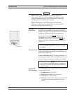
GPIB
Interconnection
The only interconnection required for GPIB opera
-
tion is between the signal generator and the control
-
ler. This interconnection is via a standard GPIB
cable. The Anritsu part number for such a cable is
2100-1, -2, or -4 (1, 2, or 4 meters in length).
GPIB Setup and Interconnection Installation
2-10 MG369XB OM