


Pulse
Modulation
Operating
Modes
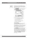
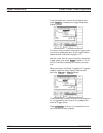
The MG369XB provides pulse modulation of the
output signal using modulating signals from either
its internal pulse generator or an external source.
To provide pulse modulation of the output signal us
-
ing a modulating signal from an external source, set
up the external pulse generator and connect it to the
MG369XB rear panel PULSE TRIG IN connector.
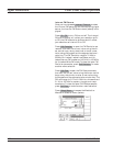
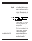
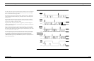
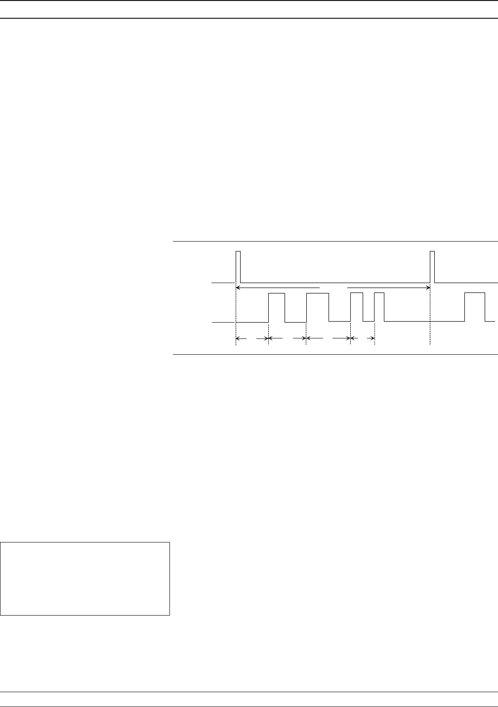
The internal pulse generator has four pulse modes–
single, doublet (double pulse), triplet (triple pulse),
and quadruplet (quadruple pulse). Individual pulse
widths (W1, W2, W3, and W4) and delays (D1, D2,
D3, and D4) can be set for each of the pulses in a
mode.
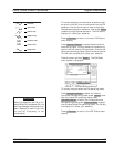
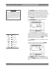
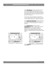
The internal pulse generator can be internally trig-
gered, externally triggered, internally and exter-
nally triggered with delay, and externally gated.
There is also a composite mode in which an external
pulse is summed with the internal pulse to pulse
modulate the output signal.
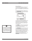
Whenever the internal pulse generator is internally
triggered, a TTL compatible signal that is synchro
-
nized to the internal pulse modulation output is
available at the rear panel PULSE SYNC OUT con
-
nector.
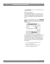
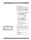
The internal pulse generator has two selectable
clock rates—100 MHz (or 40 MHz with Option 24)
and 10 MHz. The 100 MHz (or 40 MHz with
Option 24) clock rate produces higher resolution
pulses and allows higher Pulse Repetition Fre
-
quencies (PRFs); the 10 MHz clock rate produces
lower resolution pulses and lower PRFs.
External signals or pulses to trigger or gate the in
-
ternal pulse generator can be applied to the rear
panel PULSE TRIGGER IN connector.
3-106 MG369XB OM
Signal Modulation Local (Front Panel) Operation
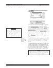
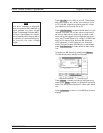
PERIOD
D1
D2
D3
OUTPUT
PULSE
SYNC OUT
W1
W2
W4 W3
D4
NOTE
40 MHz pulse clock rates are only
available with Option 24; 100 MHz
pulse clock rates are only available
with Option 26.