


A-6 MG369XB OM
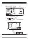
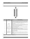
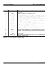
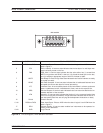
AUX I/O Connector Rear Panel Connectors
PIN SIGNAL NAME SIGNAL DESCRIPTION
11 LOCK STATUS Lock Status Output: Provides a TTL high-level signal when the frequency is
phase-locked.
12 PENLIFT Penlift: Toggles to ground for plotter penlift control.
13 EXT TRIGGER External Trigger: Accepts a TTL low-level signal of 1 ms width to trigger a sweep.
14 V/GHz V/GHz Output: Provides a reference voltage relative to the RF output frequency
(1.0 V/GHz for Model MG3692B; 0.5 V/GHz for Model MG3694B).
15 EOS INPUT End-of-Sweep Input: Accepts a TTL high-level signal to tell the signal generator
to begin the end of sweep dwell.
16 EOS OUTPUT End-of-Sweep Output: Provides a TTL high-level signal when the signal genera
-
tor has begun the end of sweep dwell.
17 AUX 1 Aux 1: Auxiliary input/output to the processor (PB6).
18 SWP DWELL IN Sweep Dwell Input: Permits a TTL low-level signal to pause the sweep. The
sweep resumes when the signal is removed.
19 AUX 2 Aux 2: Auxiliary input/output to the processor (PC3).
20 BAND SWITCH BLANK Band Switch Blanking Output: Provides a +5V or –5V signal coincident with band
switching points. Signal polarity is selected from a front panel menu.
21 SPARE
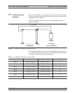
22 HORIZ IN Horizontal Sweep Input: Accepts a 0V to 10V external sweep ramp from a Master
MG369XB. This input is automatically selected when the signal generator is in the
Slave Mode.
23 RETURN Horizontal Sweep Input return.
24 GND Chassis Ground
25 MEMORY SEQ Memory Sequencing Input: Accepts a TTL low-level signal to sequence through
ten stored, front panel setups.
Figure A-2. Pin-out Diagram, AUX I/O Connector (2 of 2)