


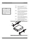
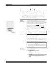
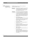

Step 9. Place the right side inner slide assembly
onto the instrument case with the handle
towards the front of the instrument.
Step 10. Insert two green-headed screws through
the holes in the slide assembly behind the
handle and into the metric tapped holes
in the side of the instrument.
Step 11. Insert two green-headed screws through
the holes near the rear of the slide assem
-
bly and into the metric tapped holes in
the side of the instrument.
Step 12. Insert the two SAE threaded screws (re
-
moved from the feet) through the 90° tabs
on the rear of the slide assembly and into
the rear panel of the instrument.
Step 13. Using the Phillips screwdriver, tighten all
screws holding the right side slide assem-
bly to the instrument chassis.
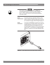
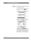
Step 14. Using the appropriate hardware, install
the outer slide assemblies onto the equip-
ment rack.
Step 15. Lift the signal generator into position.
Align the inner and outer slide assem-
blies and slide the instrument into the
rack. Realign the hardware as needed for
smooth operation.
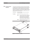
Installation Rack Mounting Kit Installation
MG369XB OM 2-7