


Chapter 4
Local Operation—Menu Maps
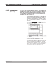
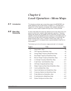
4-1 Introduction This chapter provides menu maps that support the MG369XB front
panel operating instructions found in Chapter 3. It includes menu
maps for all of the frequency and power level modes of operation. In
addition, a menu map for system configuration is also provided.
4-2 Menu Map
Description
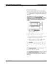
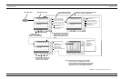
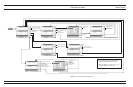
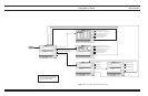
A menu map shows the menu key selections and instrument menu dis
-
plays for a particular mode of signal generator operation. The menu
displays are shown as they appear on the instrument and are linked
together to show the sequence of menu selection. A brief description of
the function of each menu's soft-keys is provided. If a menu soft-key
selects another menu, then it is shown linked to that menu. Fig-
ure 4-1, on page 4-5, is a sample menu map annotated to identify the
key elements.
The following is a list of the menu maps contained in this chapter.
Figure Title Page
4-1 Sample Menu Map ....................4-5
4-2 CW Frequency Mode Menu Map .............4-6
4-3 Analog Sweep Frequency Mode Menu Map .......4-7
4-4 Step Sweep Frequency Mode Menu Map.........4-8
4-5 Manual Sweep Frequency Mode Menu Map .......4-9
4-6 List Sweep Frequency Mode Menu Map ........4-10
4-7 Fixed Power Level Mode Menu Map ..........4-11
4-8 CW Power Sweep Mode Menu Map ...........4-12
4-9 Sweep Frequency/Step Power Mode Menu Map ....4-13
4-10 Leveling Modes Menu Map ...............4-14
4-11 Amplitude Modulation Modes Menu Map .......4-15
4-12 Frequency Modulation Mode Menu Map ........4-16
4-13 Phase Modulation Mode Menu Map ..........4-17
4-14 Pulse Modulation Mode Menu Map ...........4-18
4-15 System Configuration Menu Map ............4-19
MG369XB OM 4-3/4-4