


Rear Panel Connectors Rear Panel Index
MG369XB OM A-3
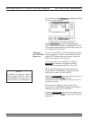
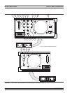
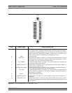
AUX I/O: 25-pin connector that provides for single cable interface with another MG369XB (master-slave
operation) or with other Anritsu instruments such as the Anritsu 56100A Scalar Network Analyzer. A
pin-out diagram for this connector is shown in Figure A-2.
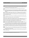
AM OUT: Provides a video modulating signal from the internal AM generator. BNC connector.
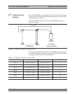
HORIZ OUT: Provides a 0V to 10V ramp during all sweep modes, regardless of sweep width. In the CW
mode, provides a voltage between 0V and 10V proportional to the full frequency range of the instrument.
When the CW Ramp is enabled, connector provides a repetitive 0V to 10V ramp. BNC connector, 50W
impedance.
10 MHz REF IN: Accepts an external 10 MHz ±100 Hz, 0 to 10 dBm time-base signal. Automatically dis-
connects the internal high-stability, time-base option, if installed. BNC connector, 50W impedance.
PULSE VIDEO OUT: Provides a video modulating signal from the internal pulse generator or external
pulse input. BNC connector.
PULSE TRIG IN: Accepts an external TTL level signal to pulse modulate the RF output. BNC connector.
10 MHz REF OUT: Provides a 0.5 Vp-p, AC coupled, 10 MHz signal derived from the internal frequency
standard of the signal generator. BNC connector, 50W impedance.
FM/FM IN: Accepts an external modulating signal (50W) to produce FM/FM on the RF output. FM/FM
sensitivity and FM/FM mode are selectable via the front panel menu or GPIB. BNC connector.
AM IN: Accepts an external modulating signal (50W) to produce AM on the RF output. AM sensitivity (Lin-
ear or Log) are selectable via the front panel menu or GPIB. BNC connector.
EXT ALC IN: Provides for leveling the RF output signal externally with either a remote detector or a
power meter. The rear panel BNC connector acceptsa0to+1Vora0to–1Vsignal.
Input Line Voltage Module: Contains an input receptacle for connecting line voltage to the MG369XB,
two 5A, type T line fuses that provide over-voltage/current protection for the signal generator’s circuits
during operation and standby, and an On/Off power switch for applying line power to the MG369XB.
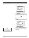
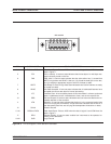
IEEE-488 GPIB: 24-pin connector that provides for remotely controlling the signal generator from an ex-
ternal controller via the IEEE488 bus (GPIB). A pin-out diagram for this connector is shown in Figure A-3.
FM/FM OUT: Provides a video modulating signal (50W) from the internal FM generator. BNC connector.
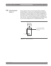
EFC: Electronic Frequency Control input accepts an external dc signal (–5V to +5V) to modulate the RF
output. Sensitivity: 10/n kHz/V where n is the reference multiplier (see page 3-80) and the modulation
bandwidth is £250 Hz. BNC connector.
PULSE SYNC OUT: Provides a TTL compatible signal synchronized to the internal pulse modulation out-
put. BNC connector.
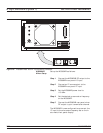
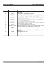
Figure A-1. Rear Panel, Series MG369XB Synthesized Signal Generator (2 of 3)
8
9
7
6
5
1
2
3
4
10
11
12
13
14
15