


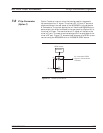


Rear Panel Connectors AUX I/O Connector
MG369XB OM A-5
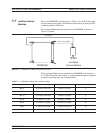
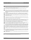
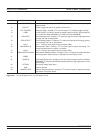
PIN SIGNAL NAME SIGNAL DESCRIPTION
1 HORIZ OUTPUT Horizontal Sweep Output: Provides a 0V at beginning and +10V at end of sweep
for all sweep modes, regardless of sweep width. In the CW mode, the voltage is
proportional to frequency between 0V at low end and +10V at the high end of
range. In CW mode, if CW Ramp is enabled, a repetitive, 0V to +10V ramp is pro
-
vided. The ramp speed is adjusted by the Sweep Time function.
2 GND Chassis Ground
3 SEQ SYNC Sequential Sync Output: Provides a +5V signal during sweep retrace, at band
switching points, and during each frequency step in step sweep mode, –5V dur
-
ing markers, and –10V during the selected marker.
4 L ALT ENABLE L-Alternate Enable Output: Provides a TTL low-level signal which indicates that
the alternate sweep mode is active.
5 MARKER OUTPUT Marker Output: Provides a +5V or –5V signal during a marker. Signal polarity se
-
lected from a front panel menu.
6 RETRACE BLANKING Retrace Blanking Output: Provides a +5V or –5V signal coincident with sweep re
-
trace. Signal polarity selected from a front panel menu.
7 L ALT SWP L-Alternate Sweep Output: Provides a TTL low-level signal to indicate that the
primary sweep is in progress or a TTL high-level signal to indicate that the alter
-
nate sweep is in progress.
8 SHIELD Cable Shield/Chassis Ground
9 TRIGGER OUTPUT Trigger Output: Provides a TTL low-level trigger signal for external devices or in
-
struments.
10 SWP DWELL OUT Sweep Dwell Output: Provides an open-collector output which goes to ground
when the sweep is dwelled at the start, stop, and band switching frequencies, and
at the markers.
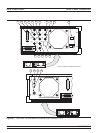
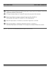
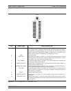
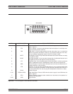
Figure A-2. Pin-out Diagram, AUX I/O Connector (1 of 2)
AUX I/O
14
15
16
17
18
19
20
21
22
23
24
1
2
3
4
5
6
7
8
9
10
11
12
13
25