


Configuring
the Rear
Panel
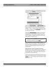
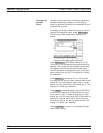
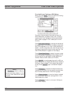
Configuring the rear panel of the signal generator
consists of selecting the polarity of the retrace
blanking, band switch blanking, retrace penlift, and
video marker outputs.
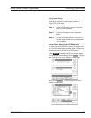
To access the Configure Rear Panel menu from the
System Configuration menu, press Rear Panel > .
The Configure Rear Panel menu (below) is dis
-
played.
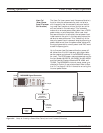
Press Blanking +/– [BPP/BPN] to select a +5V or
–5V level for the retrace and band switch blanking
outputs. The retrace and band switch blanking sig-
nal outputs are both available at the rear panel
AUX I/O connector (retrace blanking at pin 6; band
switch blanking at pin 20). The display will reflect
your selection.
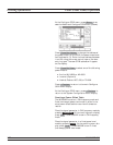
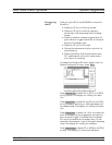
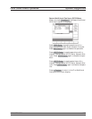
Press Marker +/– to select a +5V or –5V level for
the video marker output when video markers are se
-
lected ON. The video marker signal output is avail
-
able at the rear panel AUX I/O connector pin 5. The
display will reflect your selection.
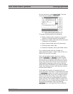
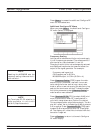
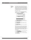
Press Penlift to select Normally Open (N/O) [PPO]
or Normally-Closed (N/C) [PPC] contacts on the in
-
ternal penlift relay. The penlift relay output, avail
-
able at pin 12 of the rear panel AUX I/O connector, is
used to lift a plotter pen at band switch points, at
filter switch points, and during sweep retrace. The
display will reflect your selection.
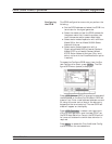
Press < Previous to return to the System Configu
-
ration menu display.
3-78 MG369XB OM
System Configuration Local (Front Panel) Operation