


Appendix A
Rear Panel Connectors
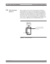
A-1 Introduction This appendix provides descriptions for the rear panel connectors on a
typical Series MG369XB Synthesized signal generator.
A-2 Rear Panel
Connectors
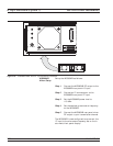
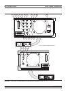
Figure A-1 provides an illustration of the rear panel and describes the
rear panel connectors.
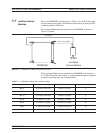
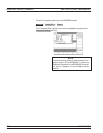
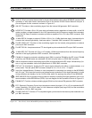
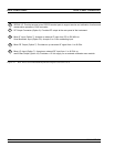
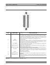
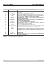
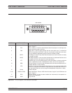
A-3 Connector Pin-out
Diagrams
Figures A-2 and A-3 provide pin-out diagrams and descriptions for the
AUX I/O and IEEE-488 GPIB multi-pin connectors on the rear panel.
MG369XB OM A-1