Reelmaster 3550−DHydraulic System Page 4 − 64
Check Hydraulic Lines and Hoses
WARNING
Keep body and hands away from pin hole leaks
or nozzles that eject hydraulic fluid under high
pressure. Use paper or cardboard, not hands, to
search for leaks. Hydraulic fluid escaping under
pressure can have sufficient force to penetrate
the skin and cause serious injury. If fluid is in-
jected into the skin, it must be surgically re-
moved within a few hours by a doctor familiar
with this type of injury. Gangrene may result from
such an injury.
IMPORTANT: Check hydraulic lines and hoses daily
for leaks, kinked lines, loose mounting supports,
wear, loose fittings or deterioration. Make all neces-
sary repairs before operating the machine.
Priming Hydraulic Pumps
Whenever the hydraulic system is flushed, the hydraulic
system is charged or hydraulic components are re-
moved, it is important to properly prime the hydraulic
pumps. Hydraulic pump priming ensures that the gear
pump and piston (traction) pump have adequate oil dur-
ing initial start−up and running. The pumps can be
primed by using a remote starter switch (see Special
Tools in this chapter) to crank engine which allows the
pumps to prime.
Use the following procedure to prime the hydraulic
pumps:
1. Make sure that ignition switch is in the OFF position
and key is removed from switch.
2. Check hydraulic reservoir oil level and adjust if ne-
cessary.
NOTE: It may not be necessary to remove the wire from
the starter solenoid B+ terminal when connecting a re-
mote starter switch.
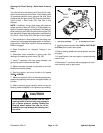
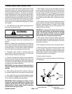
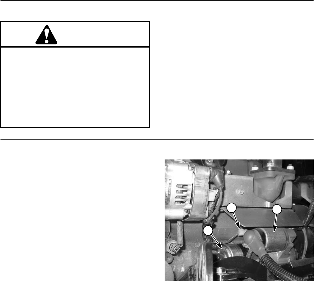
3. Connect remote starter switch electrical leads to the
starter motor solenoid B+ terminal (Fig. 40) and the pos-
itive (+) terminal at the starter or battery.
4. Engage remote starter switch and crank starter for
thirty (30) seconds to prime hydraulic pumps. Wait thirty
(30) seconds to allow the starter motor and starter
solenoid to cool. Repeat cranking procedure a second
time.
5. Disconnect remote starter switch leads from starter
motor solenoid terminal and positive post of the battery.
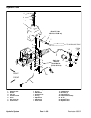
1. Starter motor
2. Starter solenoid
3. B+ terminal
Figure 40
1
2
3


