


Reelmaster 3550−D Hydraulic SystemPage 4 − 25
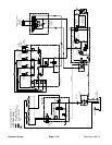
Steering Circuit
The tandem gear pump is directly coupled to the vari-
able displacement piston pump/hydrostat which is belt
driven by the engine. The rear section of the tandem
gear pump (P2) supplies hydraulic flow for the steering
circuit (priority flow), for raising and lowering the cutting
units and for the traction charge circuit. The gear pump
takes its suction from the hydraulic tank. Maximum
steering and lift circuit pressure of 1000 PSI (69 bar) is
limited by the relief valve located in the power steering
valve.
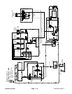
With the engine running and the steering control valve
in the centered position (steering wheel not being
turned), gear pump flow enters the steering control
valve at the P port and goes through the control valve,
by−passing the rotary meter and steering cylinder. Flow
leaves the control valve through the E port to be avail-
able for the lift circuit and then to the traction charge cir-
cuit.
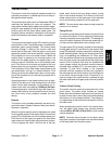
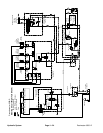
Right Turn
When a right turn is made with the engine running, the
turning of the steering wheel positions the control valve
so that flow goes through the bottom of the valve. Gear
pump flow entering the steering control valve at the P
port goes through the valve and is routed to two places.
First, most of the flow through the valve is by−passed out
the E port back through the lift control manifold and then
to the traction charge circuit. Second, the remainder of
the flow is drawn through the rotary meter in the steering
control valve and out port R to the steering cylinder. Flow
retracts the steering cylinder for a right turn. The rotary
meter ensures that the oil flow to the steering cylinder is
proportional to the amount of the steering wheel rota-
tion. Fluid leaving the steering cylinder flows back
through the steering control valve then through the T
port and then to the traction charge circuit.
The steering control valve returns to the neutral position
when turning is complete.
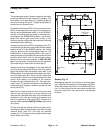
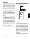
Figure 24
6.1
1000 PSI
STEERING CYLINDER
P
L
ET
R
3.79” Stroke
2.00” Bore
0.625” Rod
FROM GEAR
PUMP
TO LIFT
MANIFOLD
TO CHARGE
CIRCUIT
LEFT TURN
STEERING
CONTROL
VALVE
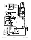
Left Turn (Fig. 24)
When a left turn is made with the engine running, the
turning of the steering wheel positions the steering con-
trol valve so that flow goes through the top of the valve.
Gear pump flow entering the steering control valve at
the P port goes through the spool and is routed to two
places. As in a right turn, most of the flow through the
valve is by−passed out the E port back through the lift
control valve and then to the traction charge circuit. Also
like a right turn, the remainder of the flow is drawn
through the rotary meter in the steering control valve but
goes out port L to the steering cylinder. Flow extends the
steering cylinder for a left turn. The rotary meter ensures
that the oil flow to the cylinder is proportional to the
amount of the turning on the steering wheel. Fluid leav-
ing the steering cylinder flows back through the steering
control valve then through the T port and then to the trac-
tion charge circuit.
The steering control valve returns to the neutral position
when turning is complete.
Hydraulic
System