


Reelmaster 3550−D Page 5 − 31 Electrical System
Seat Switch
The seat switch is normally open and closes when the
operator seat is occupied. The seat switch is located dir-
ectly under the seat.
The TEC controller monitors the position of the seat
switch (open or closed). Using inputs from the seat
switch and other switches in the interlock system, the
TEC controller controls the energizing of the engine
start relay, the fuel stop solenoid and fuel pump, the pro-
portional relief valve (PRV) used to drive the cutting unit
motors,and solenoid valves (S1, S2, S3, and S4) used
to lower and raise the cutting units (see Table 3: Input
Conditions Required to Illuminate Diagnostic Display
Outputs in this chapter).
Testing
1. Park vehicle on a level surface, stop engine, apply
parking brake and remove key from ignition switch.
2. Before disconnecting the seat switch for testing, the
switch and its circuit wiring should be tested as a TEC
electrical input using the Diagnostic Display (see Diag-
nostic Display in this chapter). If input testing verifies
that the seat switch and circuit wiring are functioning cor-
rectly, no further switch testing is necessary. If, however,
input testing determines that the seat switch and circuit
wiring are not functioning correctly, proceed with the fol-
lowing switch testing procedure.
3. A short wire harness is used to connect the seat
switch to the main wire harness. Disconnect the seat
switch harness from the main wire harness. The seat
switch harness connector is located under the seat as-
sembly between the operator’s control panel and the
seat.
4. Check the continuity of the seat switch by connecting
a multimeter (ohms setting) across the seat switch har-
ness connector terminals. With no pressure on the seat,
there should be no continuity through the switch.
5. Press directly onto the seat switch through the seat
cushion. There should be continuity through the switch
as the seat cushion approaches the bottom of its travel.
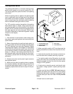
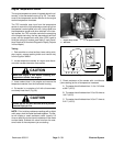
6. If the continuity test determines that the seat switch
is not operating correctly,remove the seat cushion from
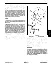
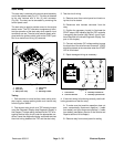
the seat chassis (Fig. 33):
A. Remove two (2) flange head screws under the
front of the seat cushion.
B. Lift front of seat cushion up then slide forward and
out of seat chassis.
1. Seat chassis
2. Seat back
3. Seat cushion
4. Flange head screw (2)
5. Seat switch harness
6. Seat switch
Figure 33
1
3
5
6
4
2
If seat switch service is necessary, remove
seat cushion from seat chassis to access
switch. DO NOT attempt to reach switch
through openings in seat chassis as edges of
openings may be sharp.
WARNING
7. Check seat switch and/or seat switch harness for
continuity. Repair or replace components as needed.
8. If the seat switch and seat switch harness tests cor-
rectly and a circuit problem still exists, check machine
wire harness (see Electrical Schematics and Wire Har-
ness Drawings in Chapter 9 - Foldout Drawings in this
manual).
9. After testing is complete, install seat cushion, con-
nect seat switch wire harness to seat switch and install
operator seat. Connect seat switch wire harness to main
wire harness and check seat switch operation.
Electrical
System