


Reelmaster 3550−D Hydraulic SystemPage 4 − 55
Steering/Lift Circuit Testing − Gear Pump (P2) Flow
Test:
Gear pump (P2) is designed to satisfy both steering cyl-
inder and lift cylinder needs simultaneously (at full
speed throttle). The Gear Pump (P2) Flow Test com-
pares fluid flow at No Load with fluid flow Under Load.
A drop in flow under load of more than 15% indicates the
gears and wear plates in the pump have worn. Contin-
ued operation with a worn pump can generate exces-
sive heat and cause damage to the seals and other
components in the hydraulic system.
If unit steering is sluggish or otherwise performs poorly,
see Steering/Lift Circuit − Steering Control Valve and
Steering Cylinder Test in this chapter.
If cutting unit lift operation is unsatisfactory, check lift
control manifold solenoid valves and/or lift cylinders.
Additional information on these components is available
in this chapter.
If both steering and lift operations perform poorly, per-
form the gear pump (P2) flow test and circuit relief valve
pressure test (see Steering/Lift Circuit − Relief Valve
Pressure Test in this chapter).
Special Equipment Required:
S Flow Meter with Pressure Gauge that has at least
a 5 GPM (16 LPM) capacity.
S Phototach (non−contact tachometer).
1. Park machine on a level surface with the cutting units
lowered and reel enable/disable switch in the disable
position. The engine should be off and the parking brake
engaged.
2. Read Precautions for Hydraulic Testing in this
chapter.
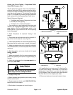
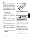
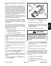
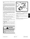
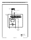
3. Disconnect hose connection on the gear pump (P2)
leading to the steering control valve (P) port (Fig. 37).
4. Install tester between gear pump and the discon-
nected hose.
5. Make sure the flow control valve on the tester is fully
open.
6. Sit in the operator’s seat and start the engine. Move
the throttle to full speed (3220 +
50 RPM).
7. Make sure hydraulic fluid is at normal operating tem-
perature by operating the machine for approximately 10
minutes.
8. Verify with a phototach that the pump speed is ap-
proximately 3090 RPM.
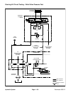
1
. Gear pump assembly 2. To steering control valv
e
(P) port
Figure 37
1
2
FRONT
RIGHT
P1
P2
9. Verify pump flow at No Load as follows:
Record tester pressure and flow readings at no load.
Unrestricted pump output should be approximately
4.2 GPM (15.8 LPM).
10.Verify pump flow Under Load as follows:
CAUTION
Do not close tester valve fully when perform-
ing this test. In this test, the hydraulic tester is
positioned before the manifold relief valve.
Pump damage can occur if the fluid flow is fully
restricted by fully closing the tester flow con-
trol valve.
A. Watch pressure gauge carefully while slowly
closing the flow control valve until 800 PSI (55.2 Bar)
is obtained on gauge.
B. Record tester pressure and flow readings under
load.
11.Set throttle to low speed and shut off engine.
12.The under load test flow reading (step 10.B) should
not drop more than 15% when compared to the no load
test flow reading (step 9.A). A difference in flow of more
than 15%, or the inability to achieve specified pressure
may indicate:
A. A restriction in the pump intake line
B. A Worn and/or slipping drive belt
C. The gear pump (P1) is worn and should be re-
paired or replaced
Hydraulic
System