


Reelmaster 3550−D Hydraulic SystemPage 4 − 109
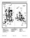
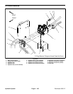
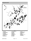
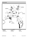
NOTE: The ports on the lift control manifold are marked
for easy identification of components. Example: S1 is
the solenoid valve and P is the supply port (see Hydrau-
lic Schematic to identify the function of the hydraulic
lines and cartridge valves at each port location).
CAUTION
Before continuing further, read and become fa-
miliar with General Precautions for Removing
and Installing Hydraulic System Components in
this section of this chapter.
WARNING
If lift manifold is attached to machine, make sure
that cutting units are fully lowered before loos-
ening hydraulic lines or cartridge valves from lift
manifold. If cutting units are raised as compo-
nents are loosened in manifold, cutting units
may drop unexpectedly.
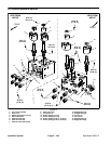
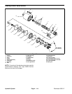
IMPORTANT: A flow control orifice is located be-
neath many of the fittings in the lift control manifold
ports. If any of the fittings is removed from the man-
ifold, make sure to remove orifice and label its posi-
tion for assembly purposes. When installing the
orifice in the manifold, make sure that the orifice is
flat in the base of the port. Manifold damage is pos-
sible if the orifice is cocked in the port.
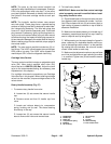
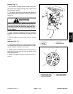
NOTE: The hydraulic manifold shown uses several
zero leak plugs. These plugs have a tapered sealing
surface on the plug head that is designed to resist vibra-
tion induced plug loosening. The zero leak plugs also
have an O−ring to provide a secondary seal. If zero leak
plug removal is necessary, lightly rap the plug head us-
ing a punch and hammer before using an allen wrench
to remove the plug: the impact will allow plug removal wi-
th less chance of damage to the socket head of the plug.
When installing plugs into the manifold, torque plugs to
the values shown.
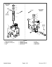
The lift control manifold includes an adjustable relief
valve (RV1). Lift control manifold relief valve (RV1)
should be set to 500 PSI (34.5 Bar). Adjust the relief
valve to the recommended setting as necessary (see
Adjustments in this chapter).
For cartridge valve service procedures, see Cartridge
Valve Service in this chapter. When installing cartridge
valves into the manifold, torque cartridge valves to the
values shown.
Hydraulic
System