


Reelmaster 3550- DPage 5 - 44Electrical System
CAN- bus Termination Resistors
System communication between electrical components
on Reelmaster 3550- D machines is accomplished on a
CAN- bus communication system. Two (2) specially de-
signed,twisted cablesform thebus forthe networkused
on themachine. These wires provide the datapathways
between machine components. At the ends of the twis-
ted pair of bus cables are two (2) 120 ohm termination
resistors.
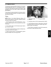
The resistors plug into the wire harness under the con-
trol panel. The resistors can be accessed by r emoving
the cover from the control panel (see Electrical Schem-
aticsand WireHarness Drawingsin Chapter8 - Foldout
Drawings in this manual for additional information). The
termination resistor and the wire harness connector
have blue inserts to identify the proper location for the
termination resistor. The resistor also has a center key-
way to prevent it from plugging into the wrong wire har-
ness connector.
IMPORTANT: The termination resistors are re-
quired for proper electrical system operation.
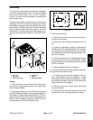
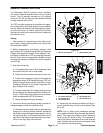
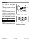
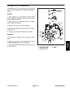
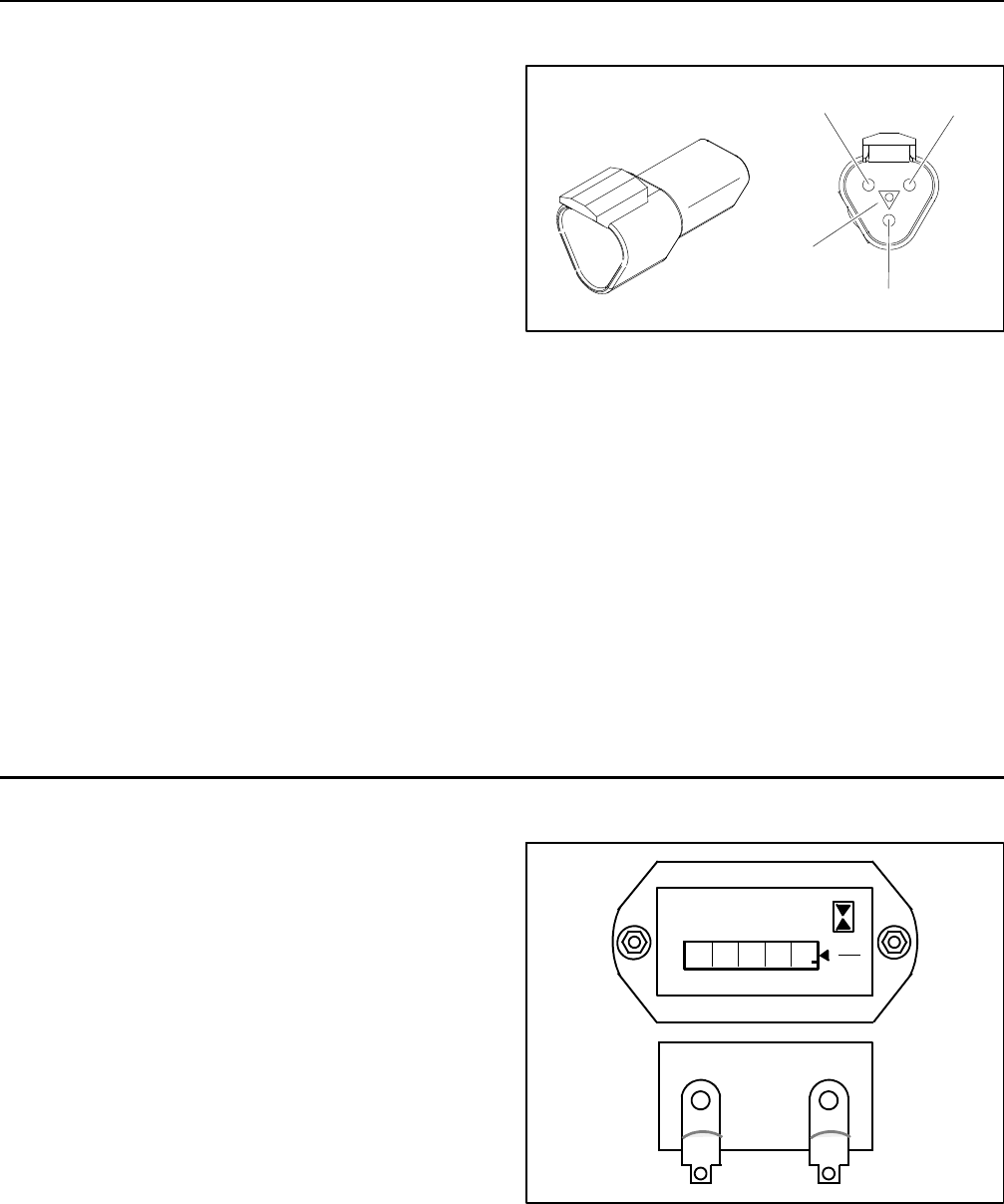
Testing
The termination resistors (Fig. 48) can be tested using
a digital multimeter (ohms setting). Thereshould be 120
ohms resistance between terminals A and B of the ter-
mination resistor. Terminal C is not used on Reelmaster
3550- D machines.
Figure 48
Termination
Resistor
A
B
C
Keyway
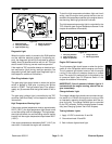
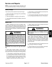
Hour Meter
The hour meter islocated onthe controlpanel. Thehour
meter (Fig. 49) indicates the total hours of machine op-
eration. The hour meter starts to function whenever the
keyswitchisintheONposition.
1. Connect the positive(+) terminalof a 12 VDCsource
to the positive terminal of the hour meter.
2. Connect the negative (- ) terminal of the voltage
source to the other terminal of the hour meter.
3. The hour meter should move 1/1 0 of an hour in six
minutes.
4. Disconnect the voltage source from the hour meter.
Figure 49
QUARTZ
Hobbs
HOURS
1
0000
1
10
+
BACK