


Reelmaster 3550−D Hydraulic SystemPage 4 − 91
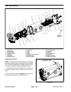
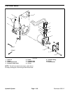
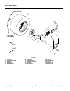
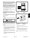
Removal (Fig. 57)
1. Park machine on a level surface. Lower cutting units,
stop engine and engage parking brake. Remove key
from the ignition switch.
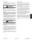
WARNING
Before jacking up the machine, review and follow
Jacking Instructions in Chapter 1 − Safety.
2. Jack up rear of equipment enough to allow the re-
moval of the rear wheel.
3. Remove rear wheel assembly from machine.
4. Thoroughly clean hydraulic hose ends and rear
wheel motor fittings to prevent hydraulic system con-
tamination.
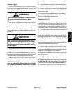
WARNING
Before disconnecting or performing any work on
the hydraulic system, all pressure in the system
must be relieved. See Relieving Hydraulic Sys
-
tem Pressure in the General Information section
of this chapter.
5. Disconnect hydraulic hoses from fittings on wheel
motor. Plug hose openings to prevent contamination.
6. Remove four (4) socket head screws and lock nuts
that secure rear wheel motor to rear fork. Remove wheel
motor with wheel hub attached from the rear fork.
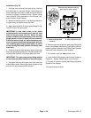
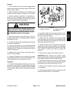
7. Secure wheel hub in a vise. Loosen but do not re-
move lock nut that secures wheel hub to wheel motor.
IMPORTANT: DO NOT hit wheel hub, wheel hub
puller or wheel motor with a hammer during wheel
hub removal or installation. Hammering may cause
damage to the wheel motor.
8. Using hub puller (see Special Tools in this chapter),
loosen wheel hub from wheel motor.
9. Remove wheel hub and motor from vise. Remove
lock nut and wheel hub from motor shaft. Locate and re-
trieve woodruff key.
10.If hydraulic fittings are to be removed from wheel mo-
tor, mark fitting orientation to allow correct assembly.
Discard O−rings from removed fittings.
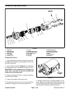
Installation (Fig. 57)
1. If fittings were removed from rear wheel motor, lubri-
cate and place new O−rings onto fittings. Install fittings
into motor openings using marks made during the re-
moval process to properly orientate fittings. Tighten fit-
tings (see Hydraulic Fitting Installation in this chapter).
2. Thoroughly clean wheel motor shaft and wheel hub
taper.
3. Lock wheel hub in a vise. Install woodruff key into the
wheel motor shaft. Slide motor shaft into hub and secure
with lock nut. Torque lock nut from 250 to 275 ft−lb (339
to 372 N−m). Remove wheel motor and hub from vise.
4. Position wheel motor with wheel hub attached to the
rear fork. Secure rear wheel motor to rear fork with four
(4) socket head screws and lock nuts.
5. Remove caps and plugs from wheel motor fittings
and hoses. Using labels placed during motor removal,
properly connect hydraulic lines to motor (see Hydraulic
Hose and Tube Installation in this chapter).
6. Install wheel assembly to machine and secure with
four (4) lug nuts.
7. Lower the machine to the ground.
8. Make sure that lock nut is torqued from 250 to 275
ft−lb (339 to 372 N−m). Also, make sure that wheel lug
nuts are torqued from 45 to 65 ft−lb (61 to 88 N−m).
9. Make sure hydraulic tank is full. Add correct oil if ne-
cessary.
Hydraulic
System